François
-
Posts
392 -
Joined
-
Last visited
Content Type
Profiles
Forums
Events
Gallery
Everything posted by François
-

Marvel's Hydra coupe 1/12 scale full scratch build
François replied to François's topic in WIP: Model Cars
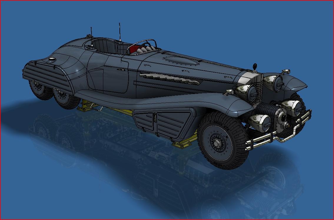
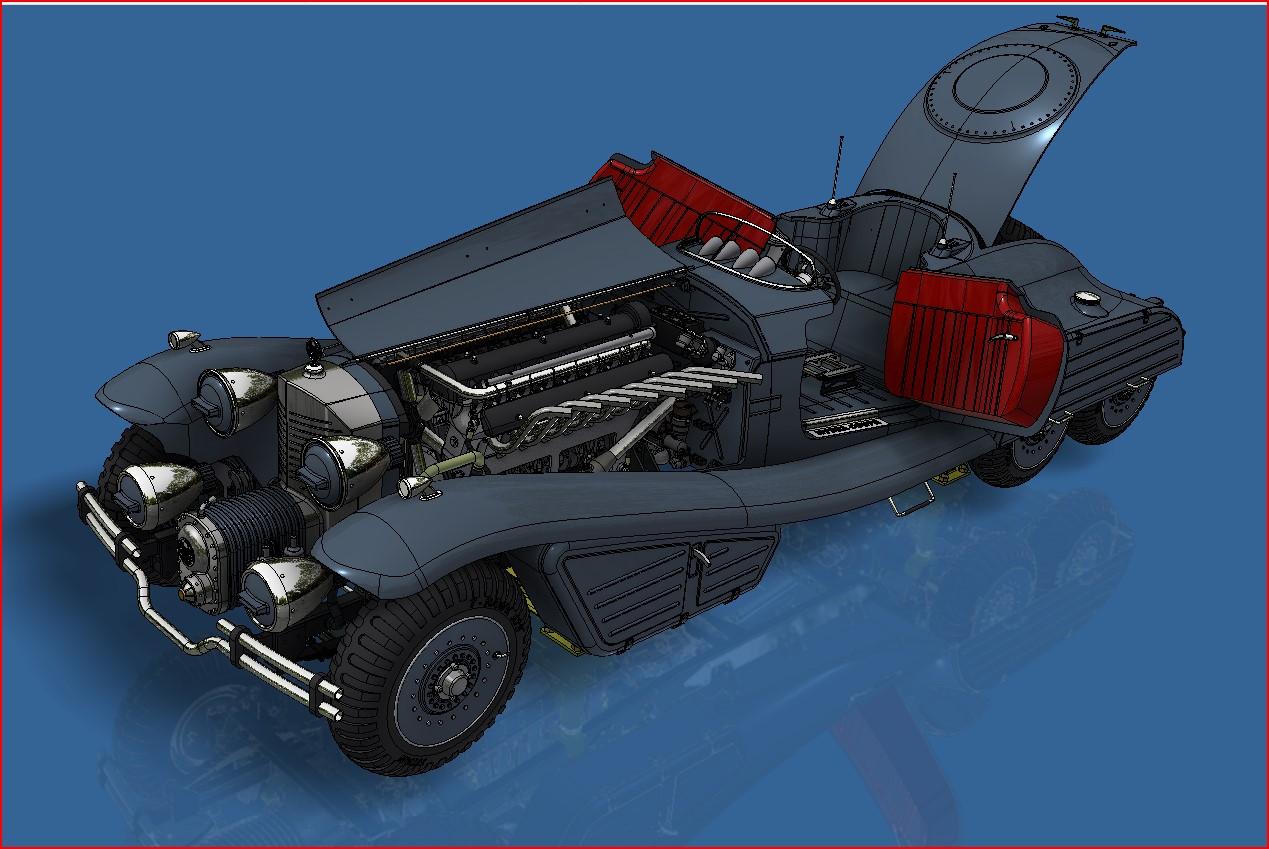
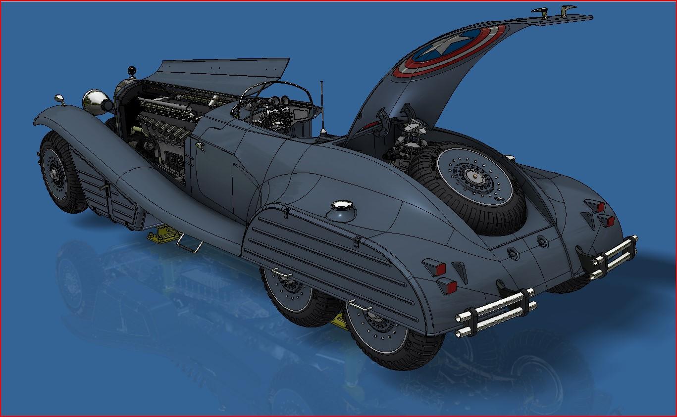
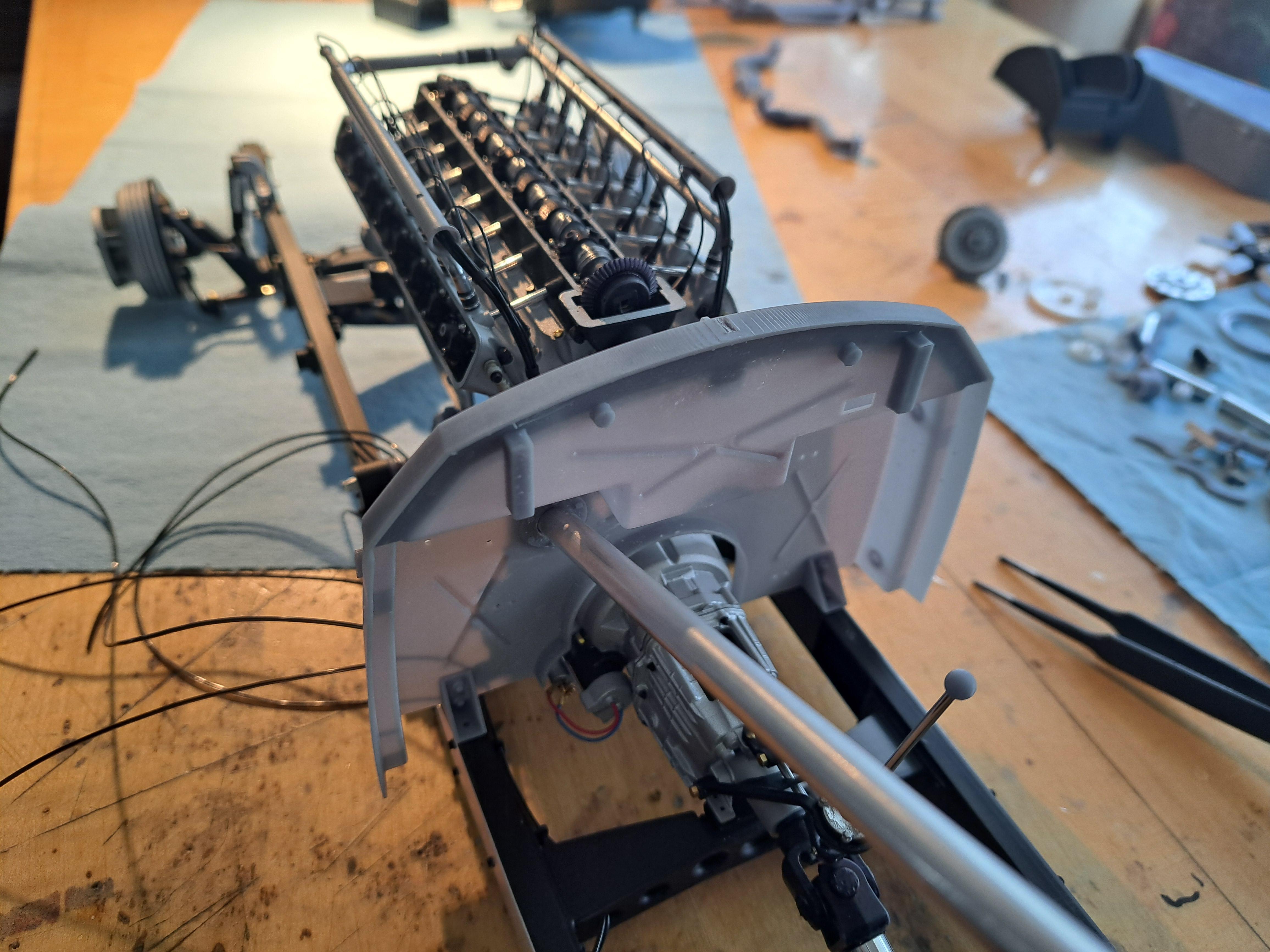
Thank you everyone for your positive comments and insights. So here's the 3d model showing the modified left front body panel that give a good view of the engine. And when seen from the other side
-
Marvel's Hydra coupe 1/12 scale full scratch build
François replied to François's topic in WIP: Model Cars
Absmiami, I've already used clear resin but it's not 100% translucide, I would even say it's a far cry from being translucide so that's a no. I post on 3 different forums and explained on all 3 my conundrum. I received plenty on interesting ideas (including yours). But there's one that I think will be best. I'll but the body on the rolling chassis but I'll modify one of the front lower panels to give a good view of the motor and all the bits and pieces that are worth seeing, probably on the steering column side. The underside of the model could be seen by reflexion on a mirored floor. I can also raise the hoods to give an even better view. I slightly modified the body to be able to lift it from the frame if need be. With this solution, I get the best of both worlds, a good view of the fun moving stuff and the great looks of the body on the frame with the wheels and all the trimming. I'll post à pictures of the 3d model showing all this soon. -
Marvel's Hydra coupe 1/12 scale full scratch build
François replied to François's topic in WIP: Model Cars
For those who wonder why I hesitate in hiding the rolling frame, here's a reminder. 20250418_215155.mp4 I just can't hide all this neat stuff. -
Marvel's Hydra coupe 1/12 scale full scratch build
François replied to François's topic in WIP: Model Cars
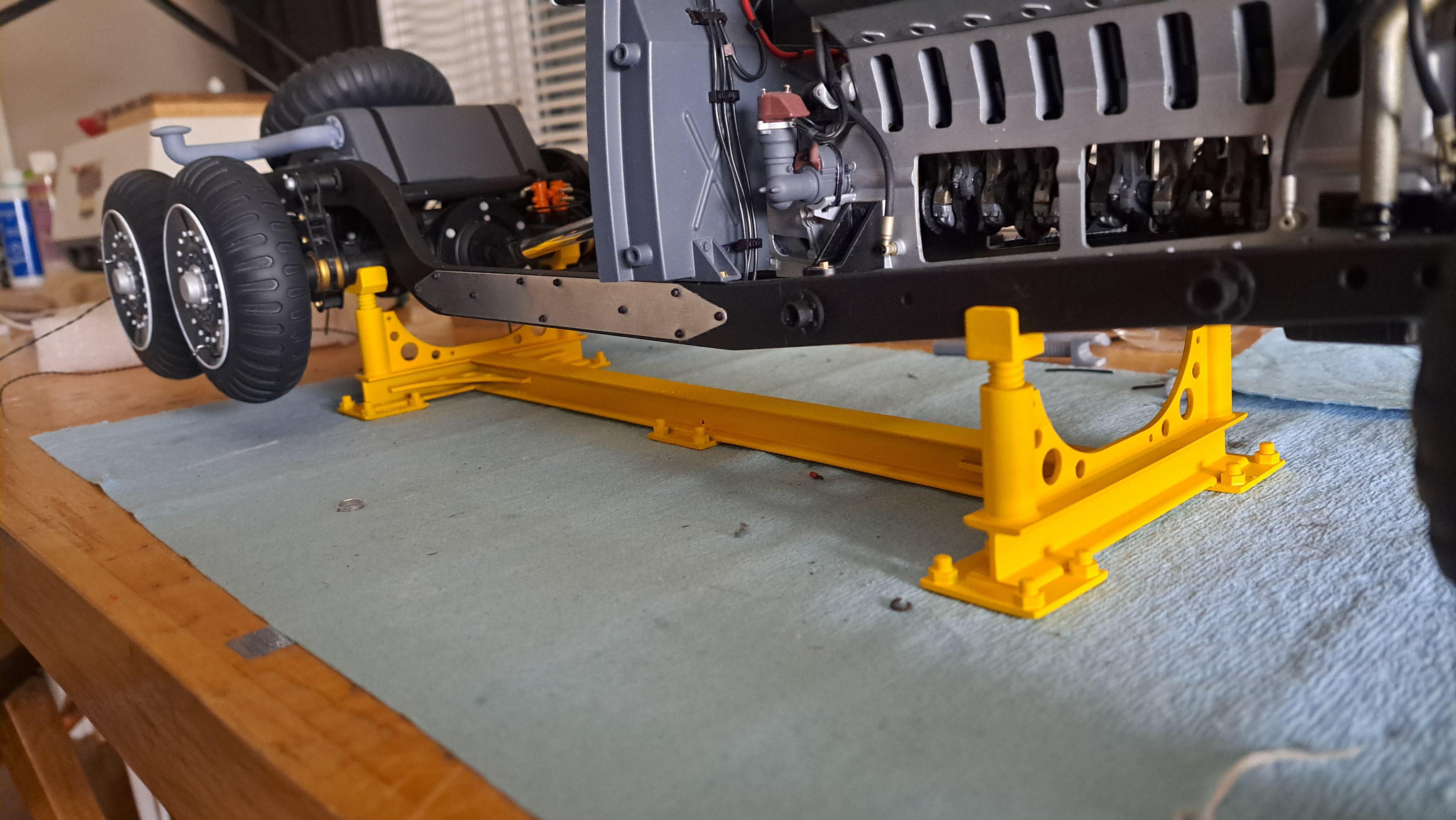
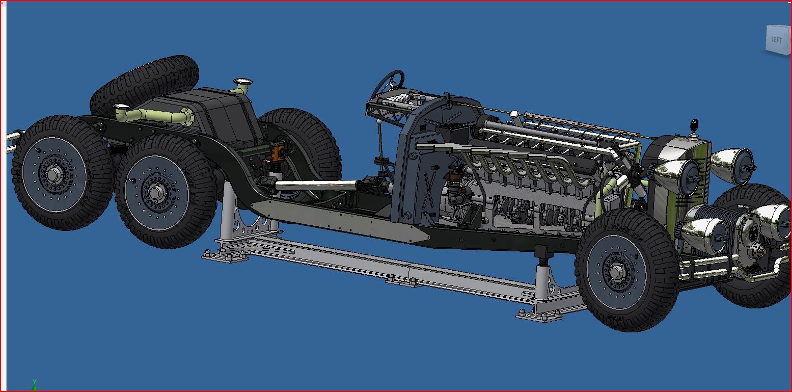
That's pretty much what I intend to do. I might redo the the yellow support go incorporate a upper rack to hold the body. I'll design the new support and post à picture shortly. -
Marvel's Hydra coupe 1/12 scale full scratch build
François replied to François's topic in WIP: Model Cars
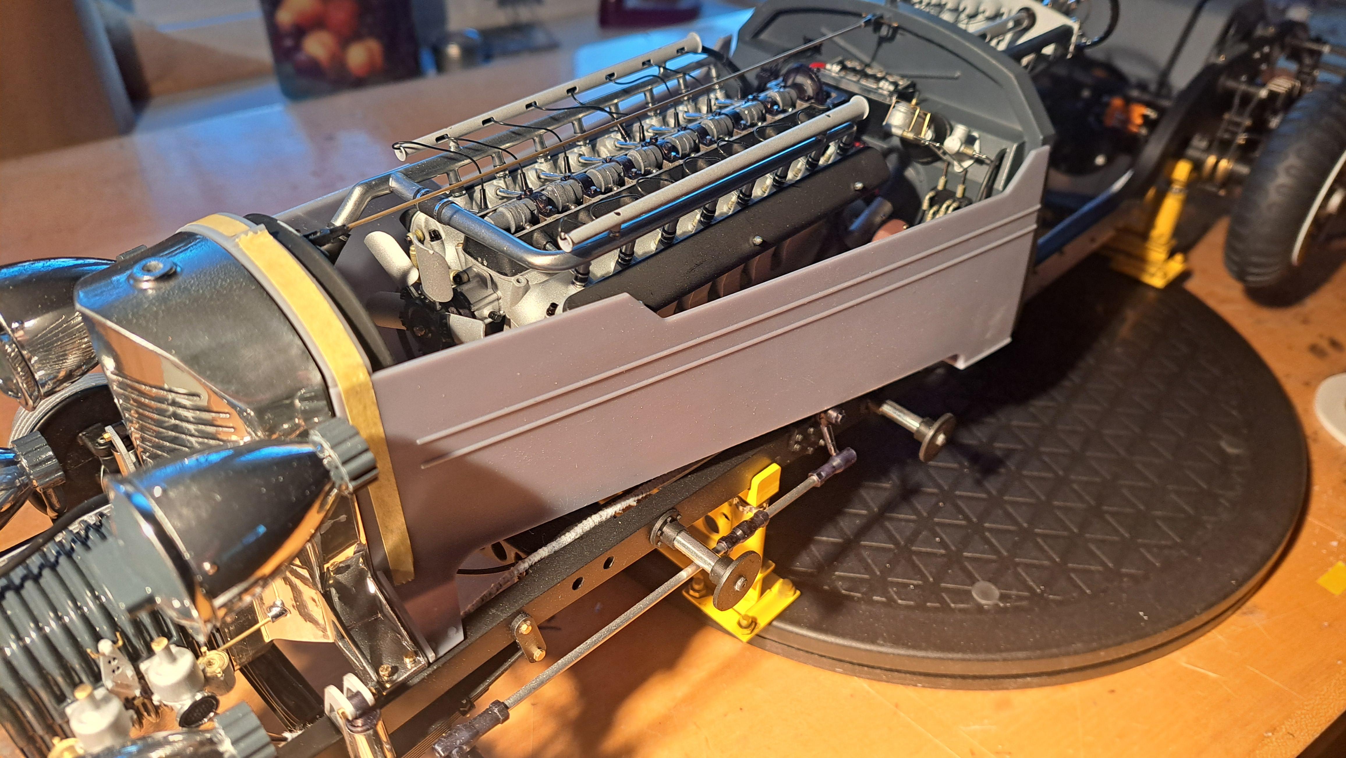
First body panel test. I have a bit of a conundrum. Do l make the complete body and install it on the frame and hide everything ? Do I make a second frame (without any mecanical components on it) to hold the body? Do I make a half body mounted on the completed frame? I'm really not sure where to go with this.
-
Marvel's Hydra coupe 1/12 scale full scratch build
François replied to François's topic in WIP: Model Cars
I decided to go with yellow for the model stand. Reminds me of the large assembly jig I saw at Canadair (became Bombardier aeronautics) back in tge early 80's on during my first summer job.
-
Marvel's Hydra coupe 1/12 scale full scratch build
François replied to François's topic in WIP: Model Cars
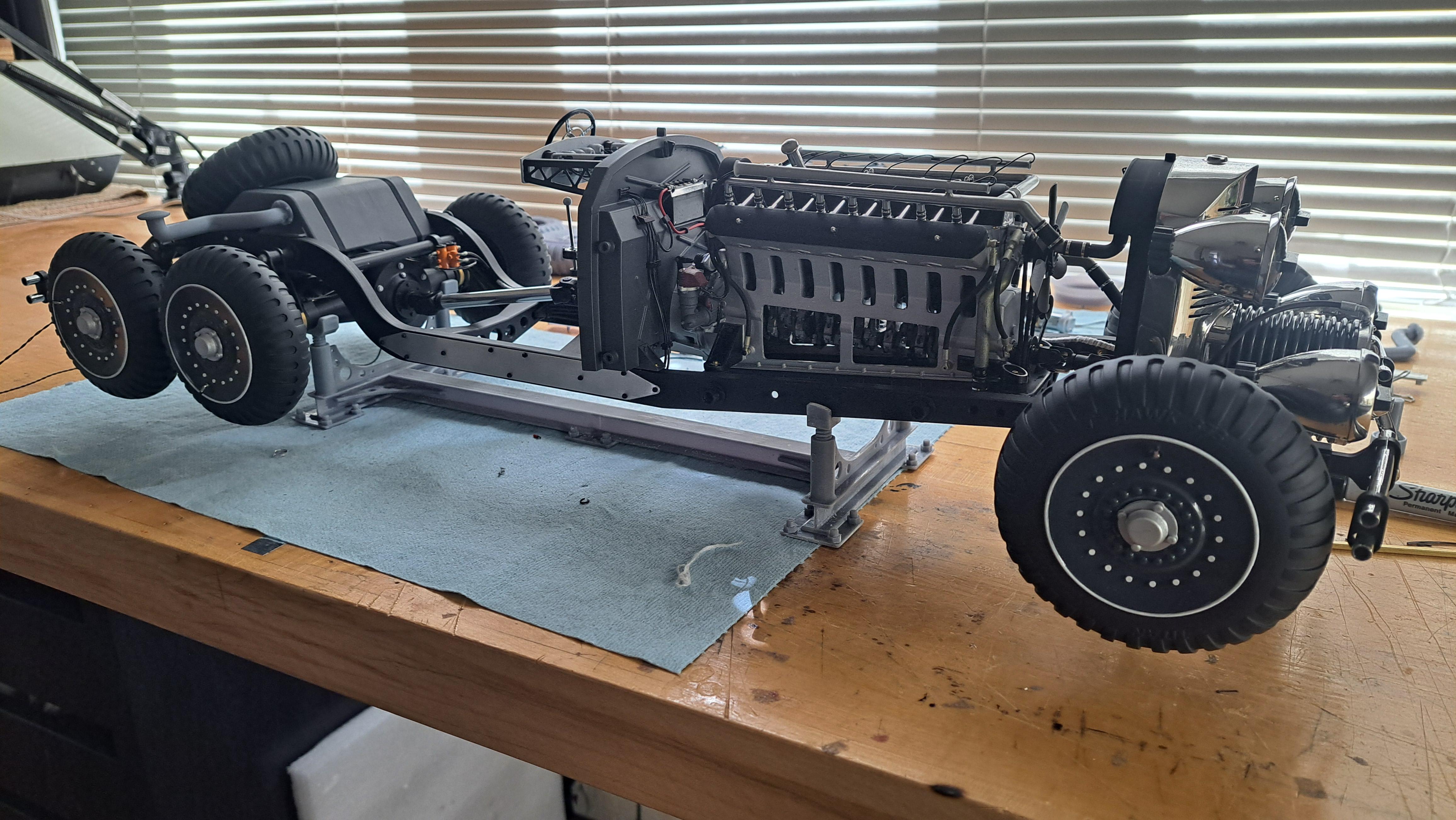
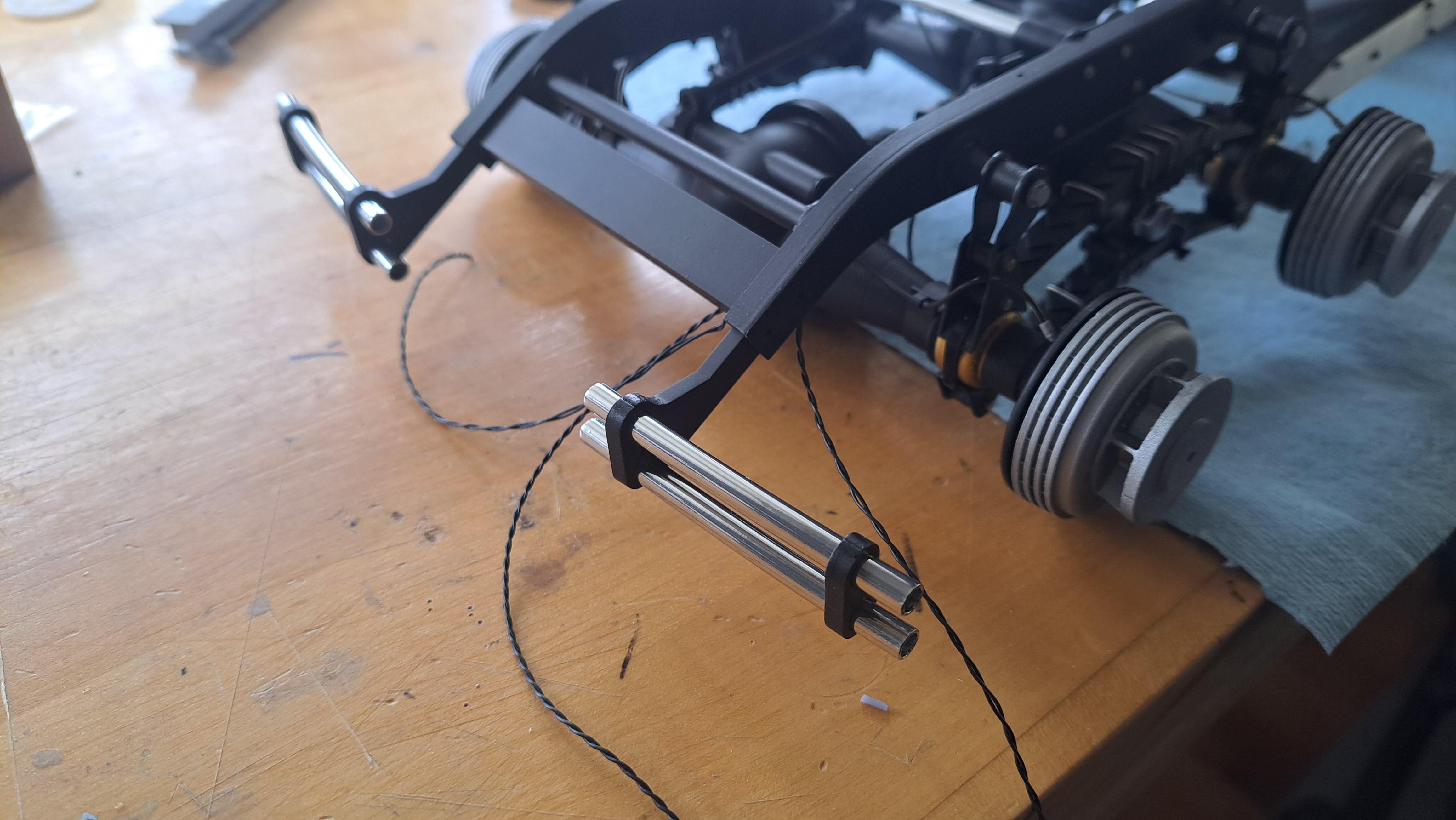
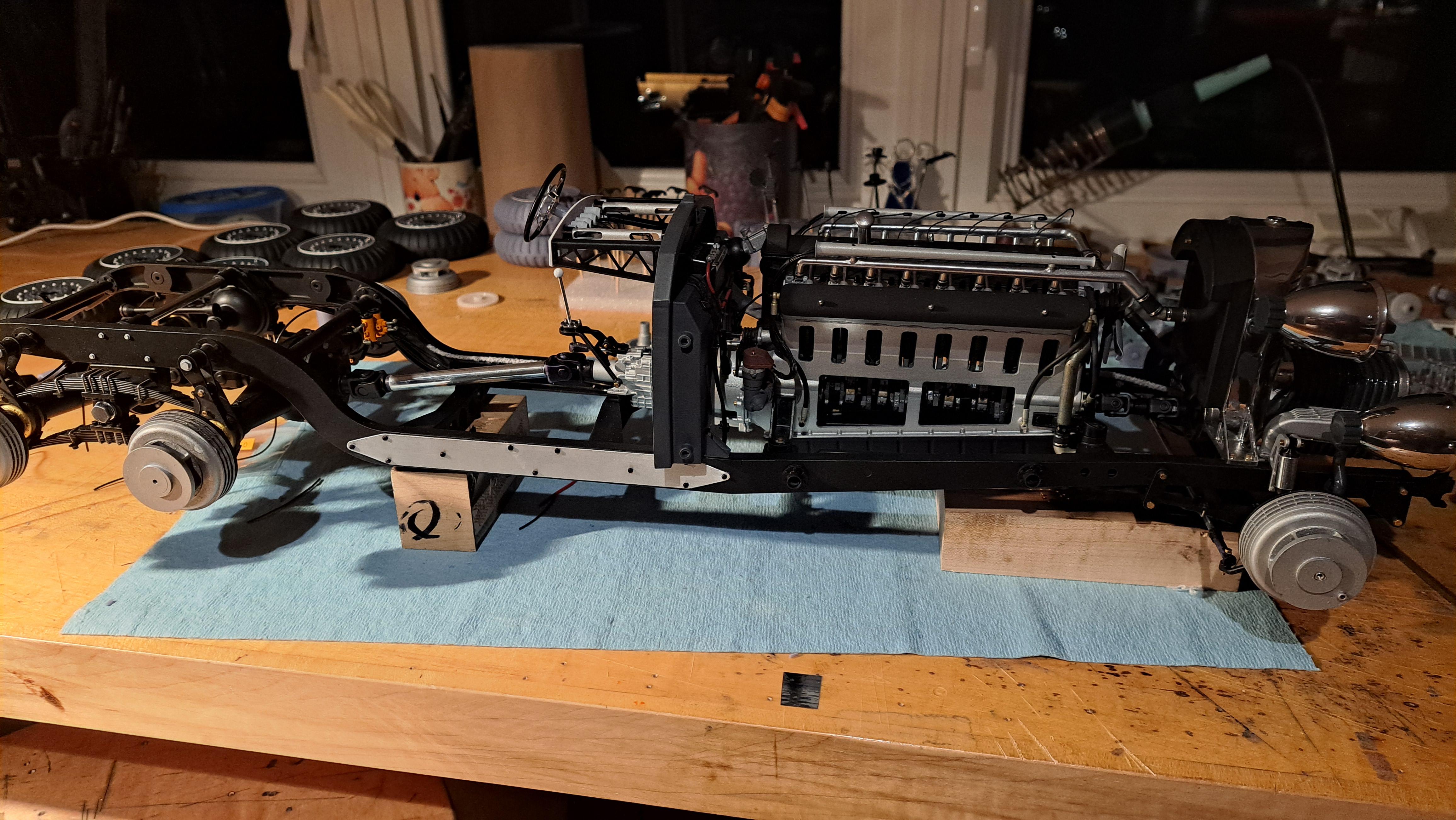
Thank you all for the nice comments. Bainford, yes it is much more impressive in person, pictures can't do it justice. Big John, kraken tentacles would be nice but I think I'll stick with the stand I made. It will eventualy be part of the display case which should have a similar Dr Doom/vilain look. It's not all clear in my head yet but it's slowly forming. Anyway, I'm still a long way from doing the case. I just installed the front and rear bumpers so that pretty much completes the frame assembly. The completed frame is now on it's stand (which still needs to be painted).
-
Marvel's Hydra coupe 1/12 scale full scratch build
François replied to François's topic in WIP: Model Cars
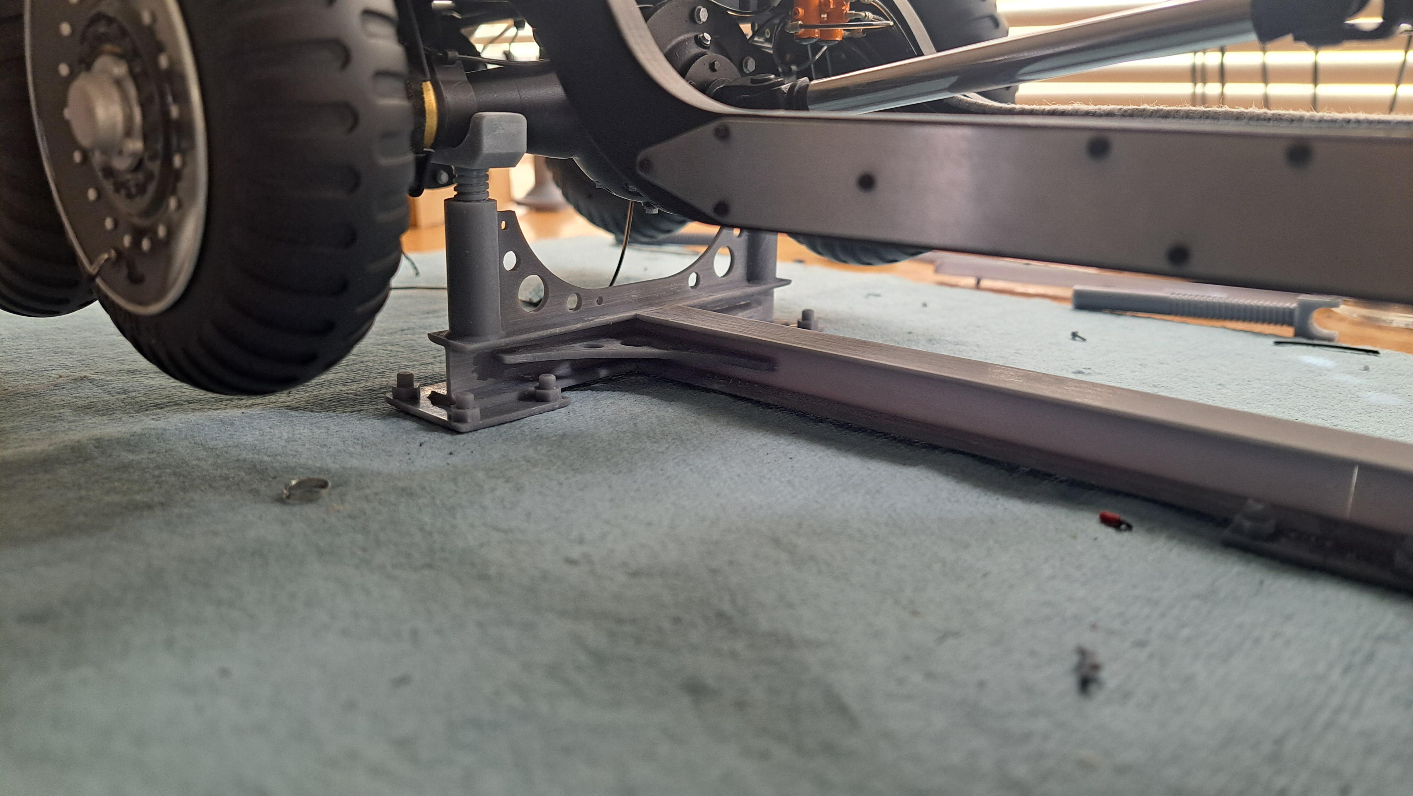
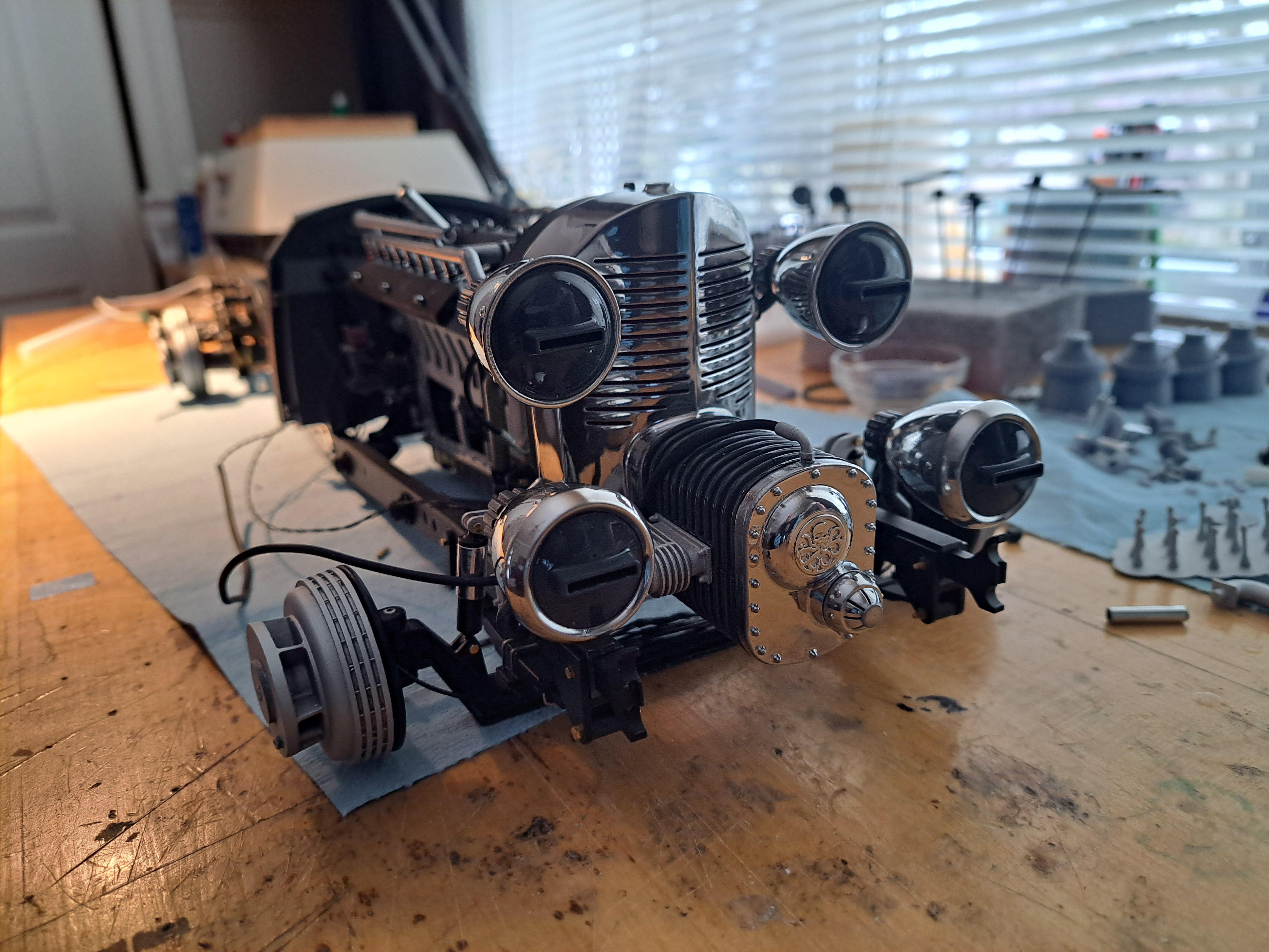
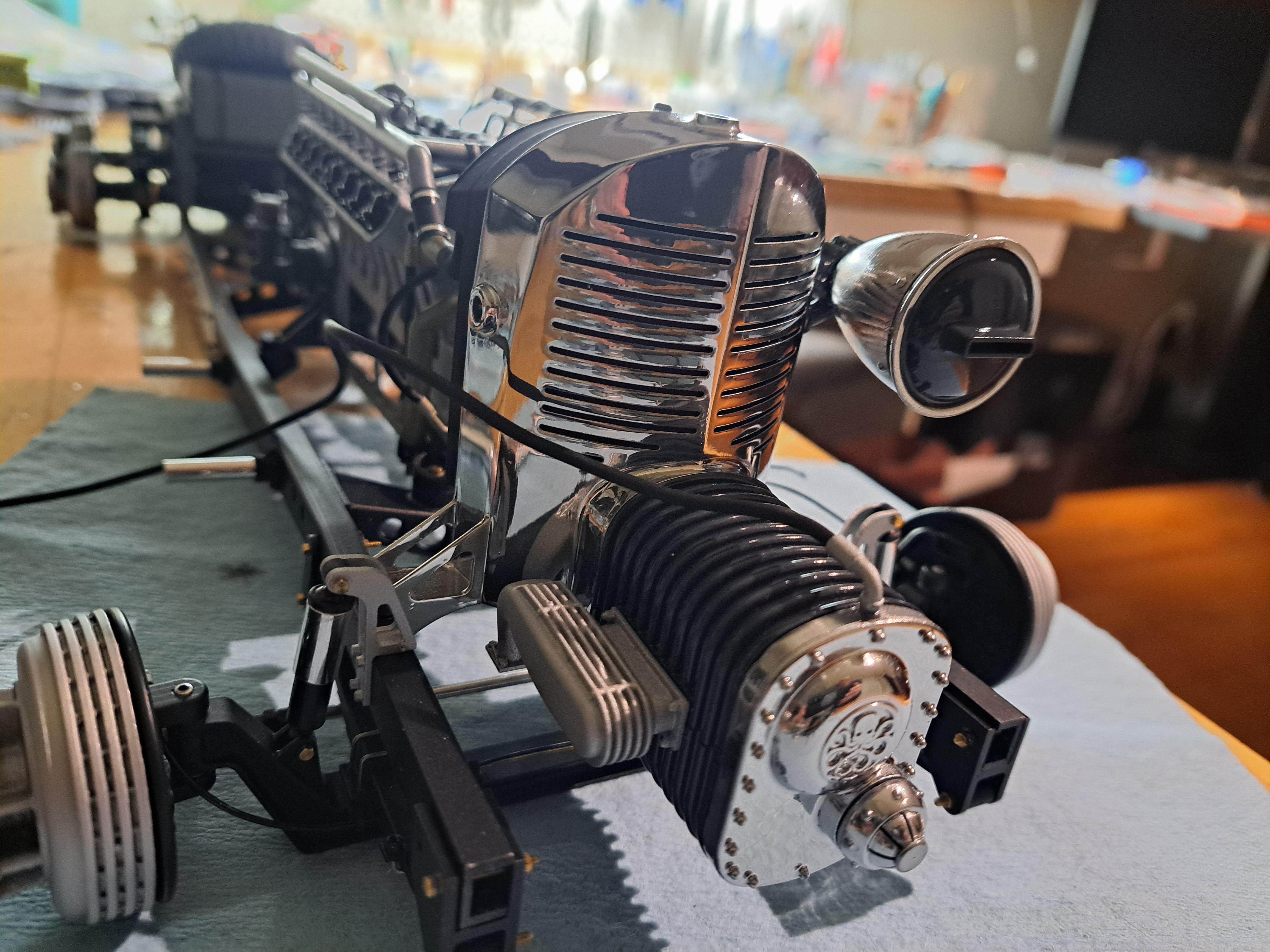
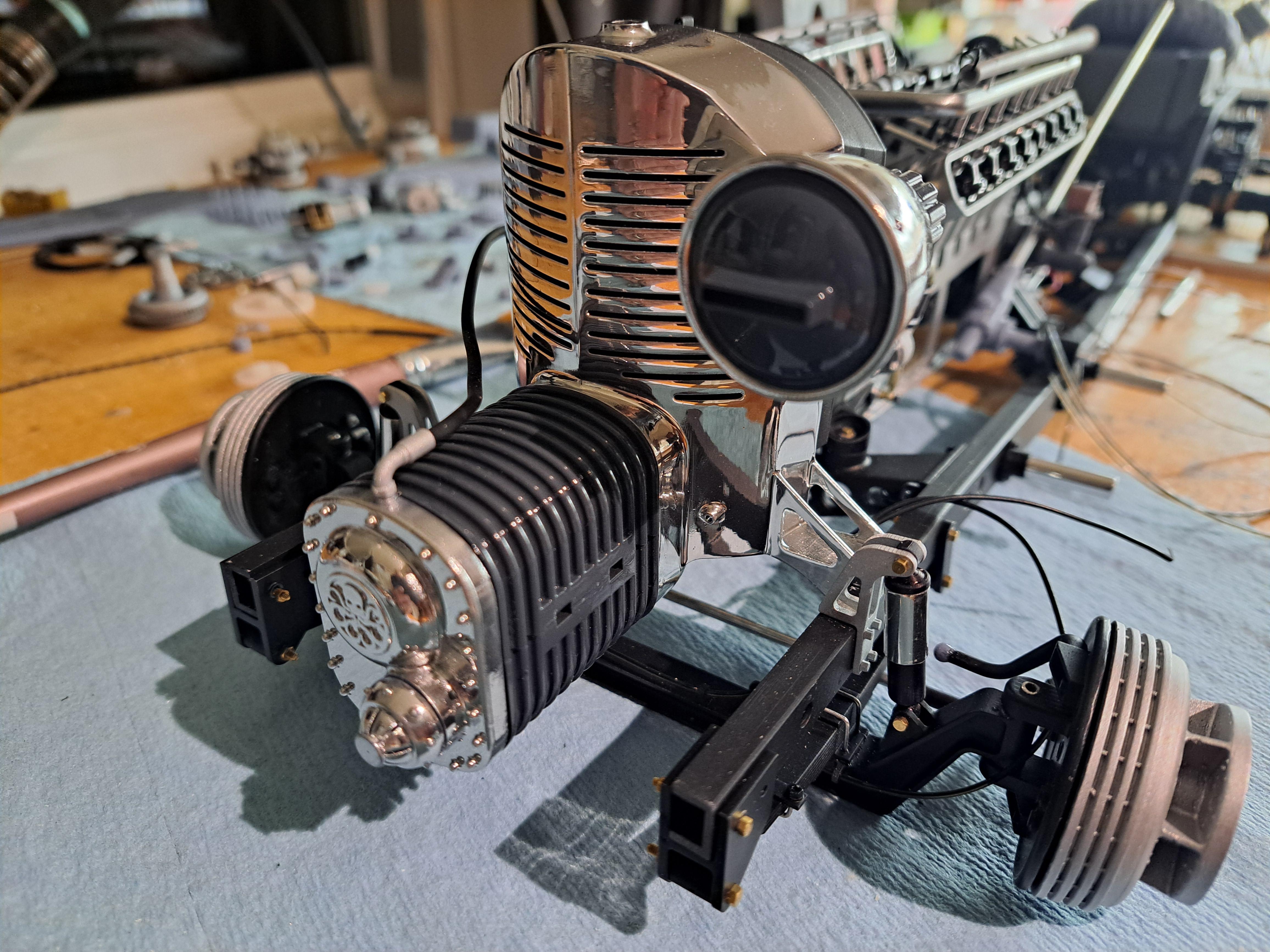
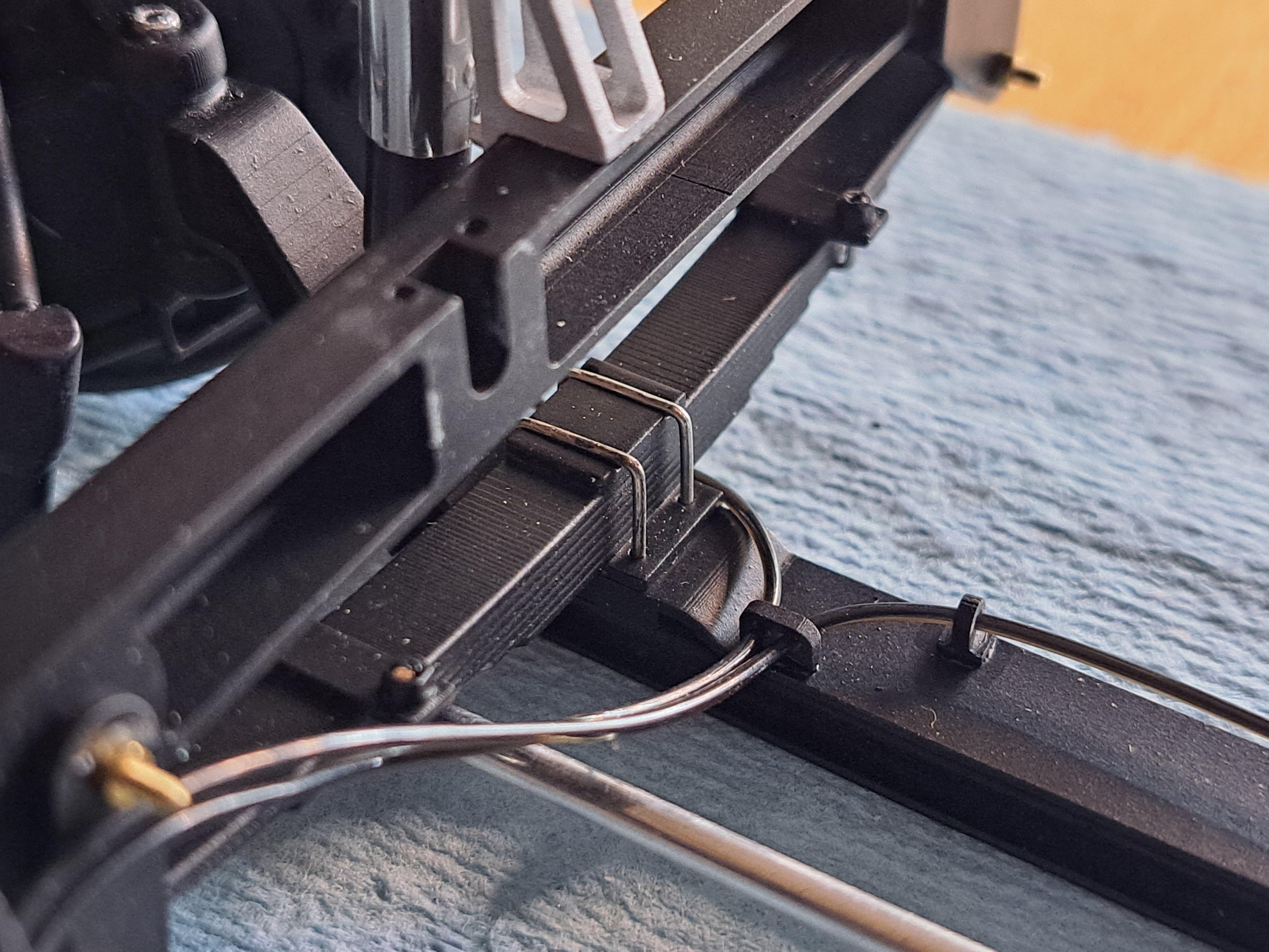
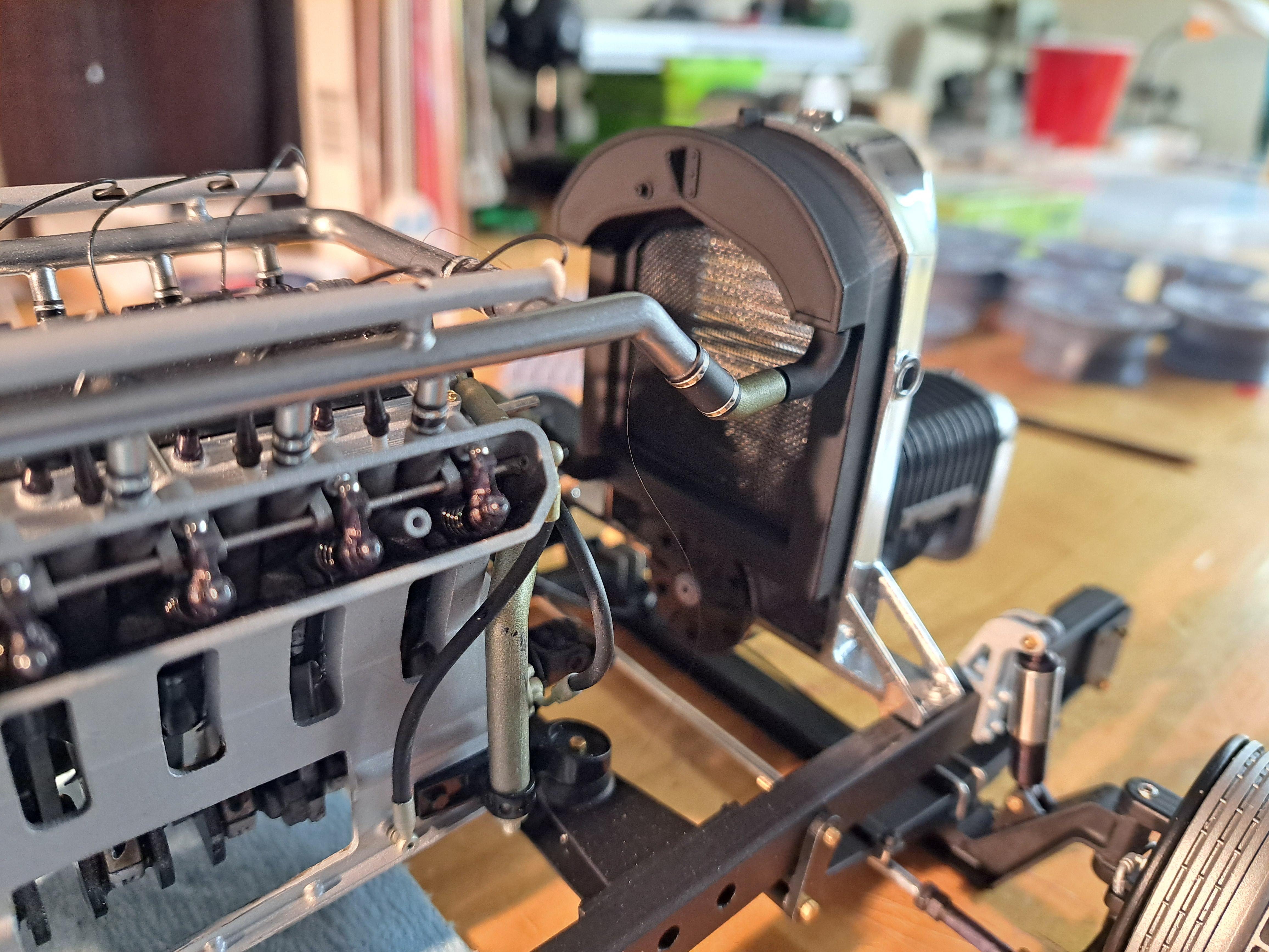
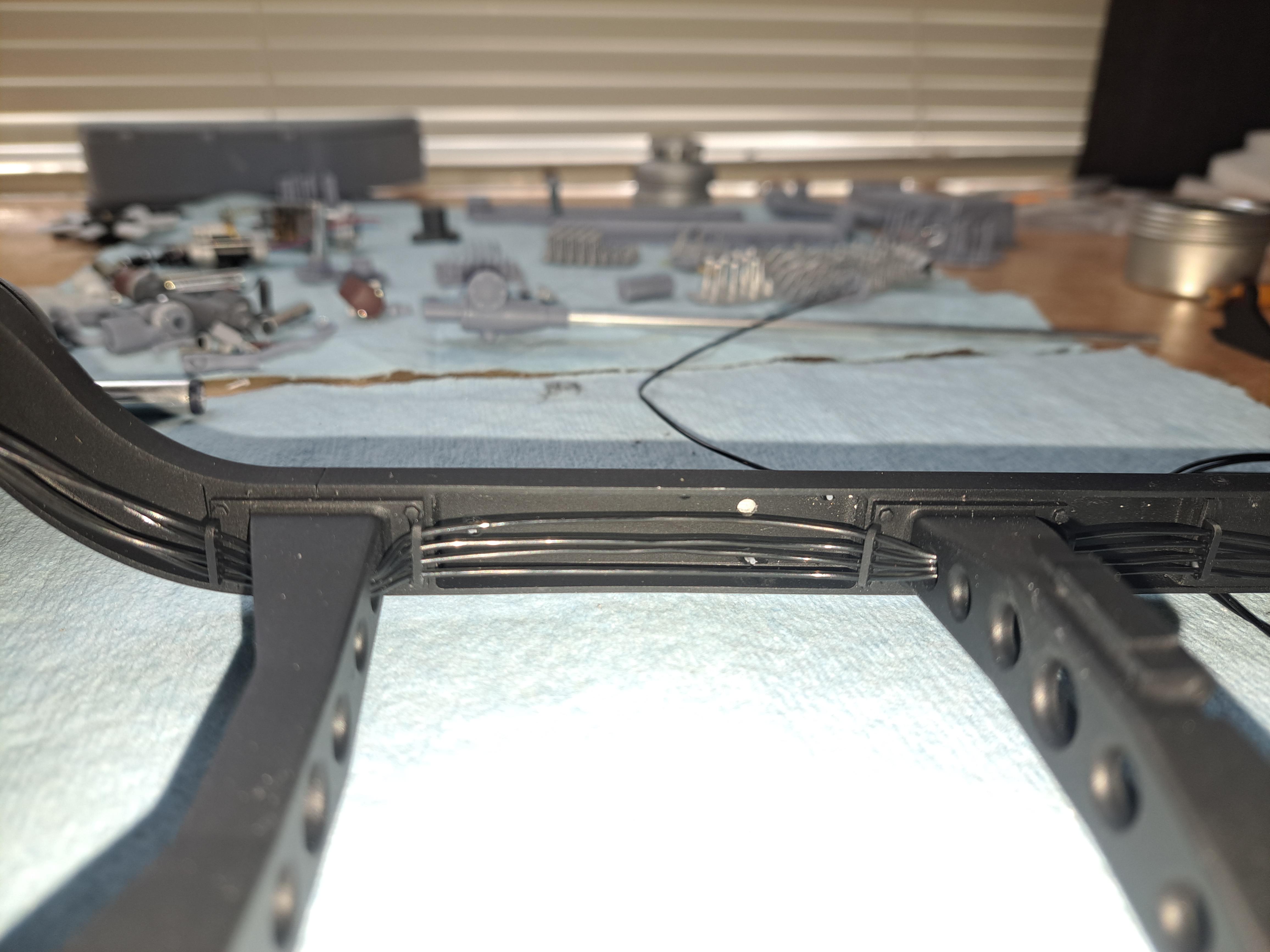
I fitted the carburators to the blower and with that done, the radiator assembly is now complete and was bolted on the frame. I could then route the head lights and gearmotor wires all the way to the back and hook up the fuel lines to the carbs. Carburators on blower Completed radiator assembly bolted on frame Wire routing Fuel line hooked up (Viewed from under) Before going any further, I decided to make a rack to hold the model so the the weight is not on the wheels and to ensure a more stable position. Model on wooden block just doesn't cut it Newly designed stand
-
Marvel's Hydra coupe 1/12 scale full scratch build
François replied to François's topic in WIP: Model Cars
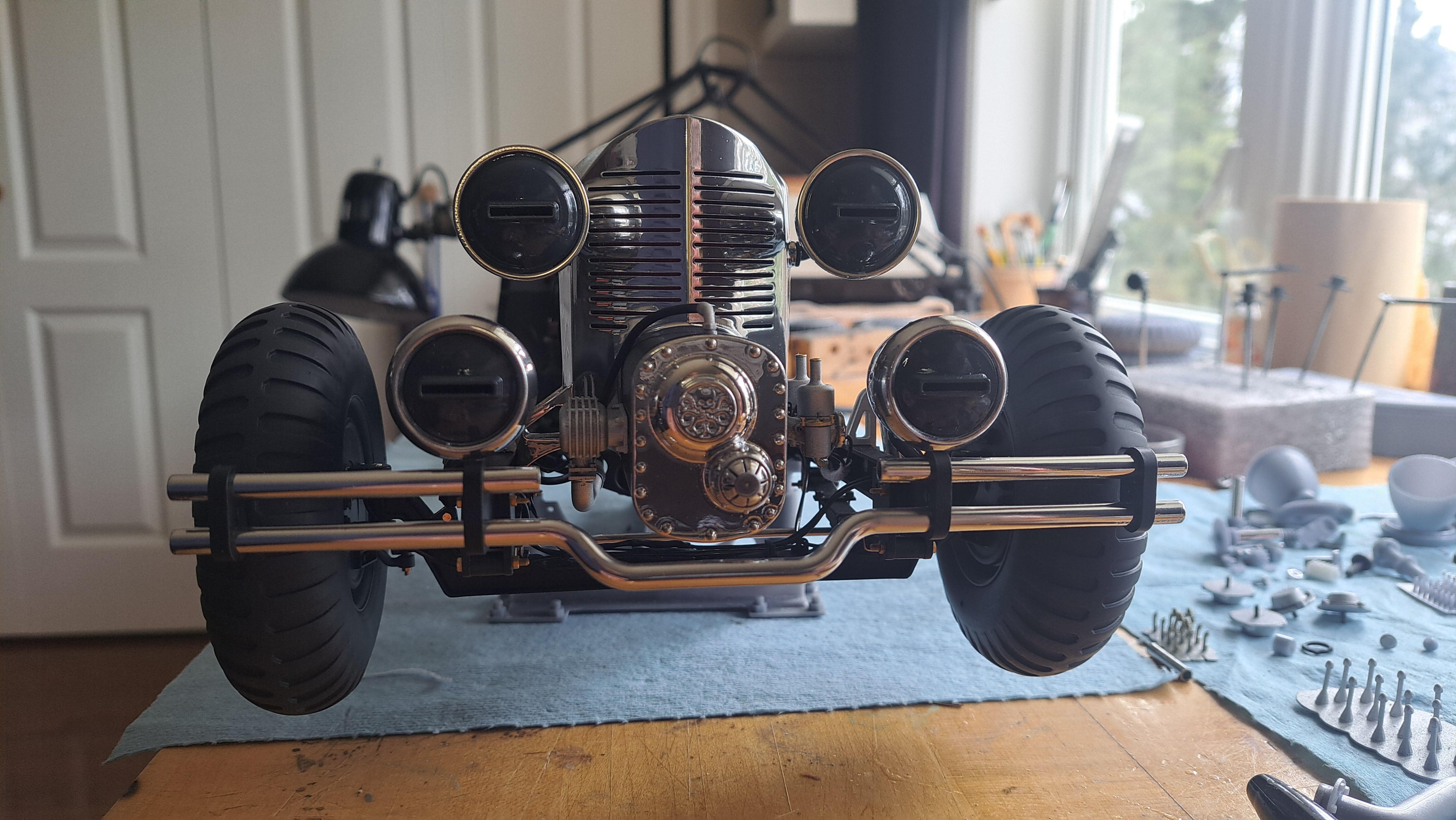
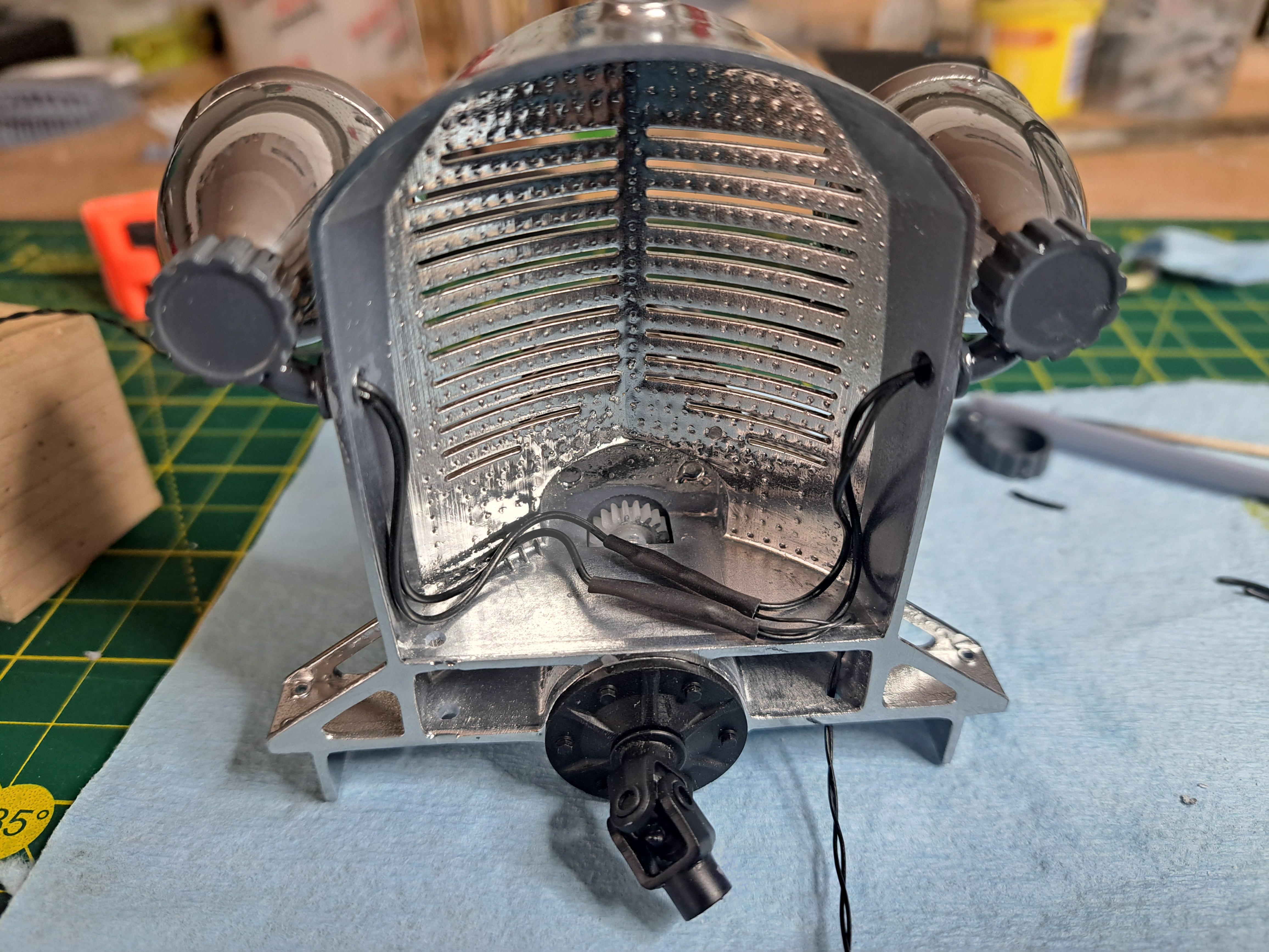
A few more boxes were checked today, fuel pump and fuel hose installed Head lights with wires installed Radiator completed And installed on frame Functionning Head lights
-
Marvel's Hydra coupe 1/12 scale full scratch build
François replied to François's topic in WIP: Model Cars
Thanks big John, I based my design on the Auto Union V16 for the mecanical aspect but also on the modern bugatti v16 for the firing sequence which is as follows: 1-5-9-13-2-6-10-14-3-7-11-15-4-8-12-16 -
Marvel's Hydra coupe 1/12 scale full scratch build
François replied to François's topic in WIP: Model Cars
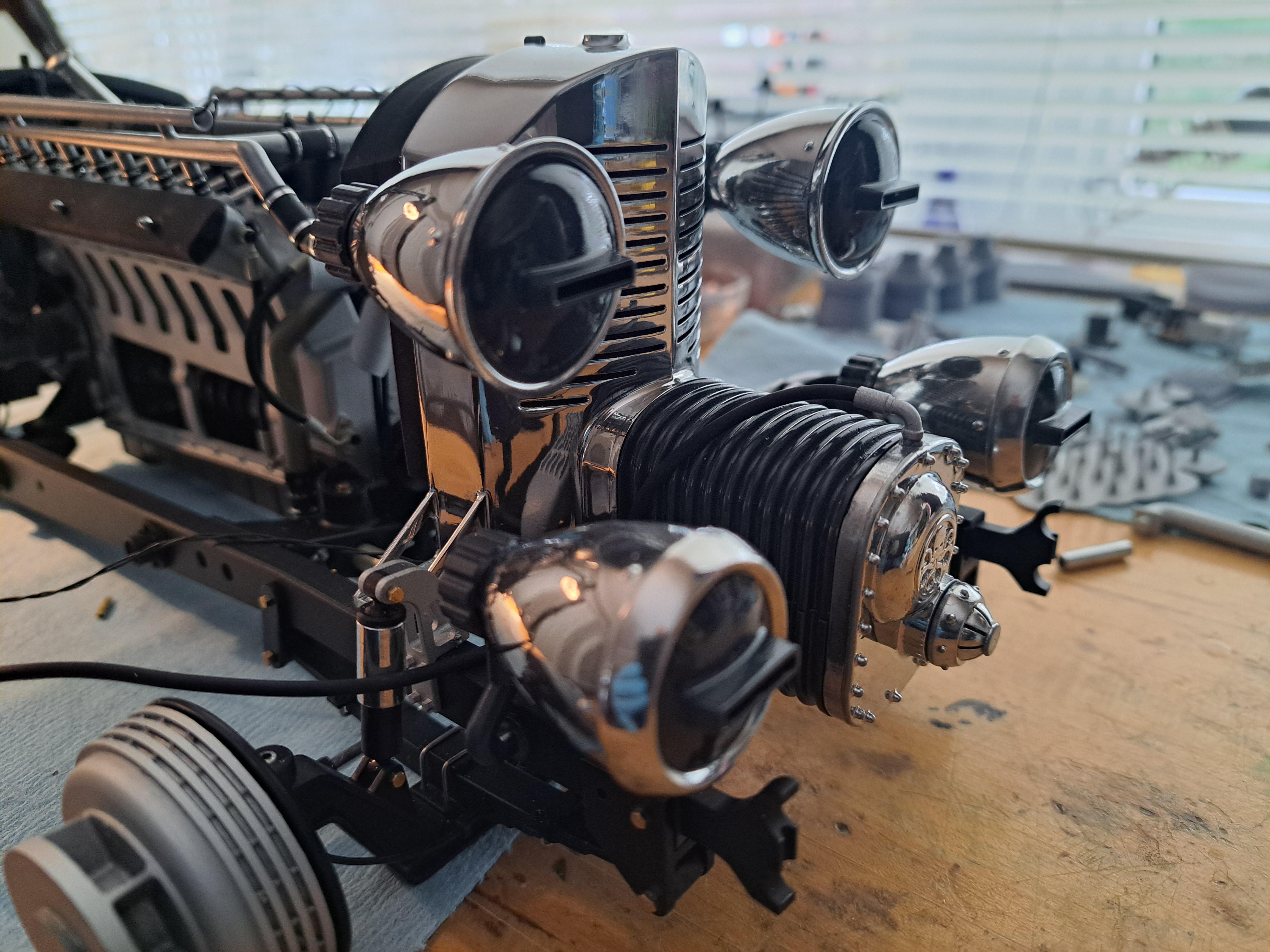
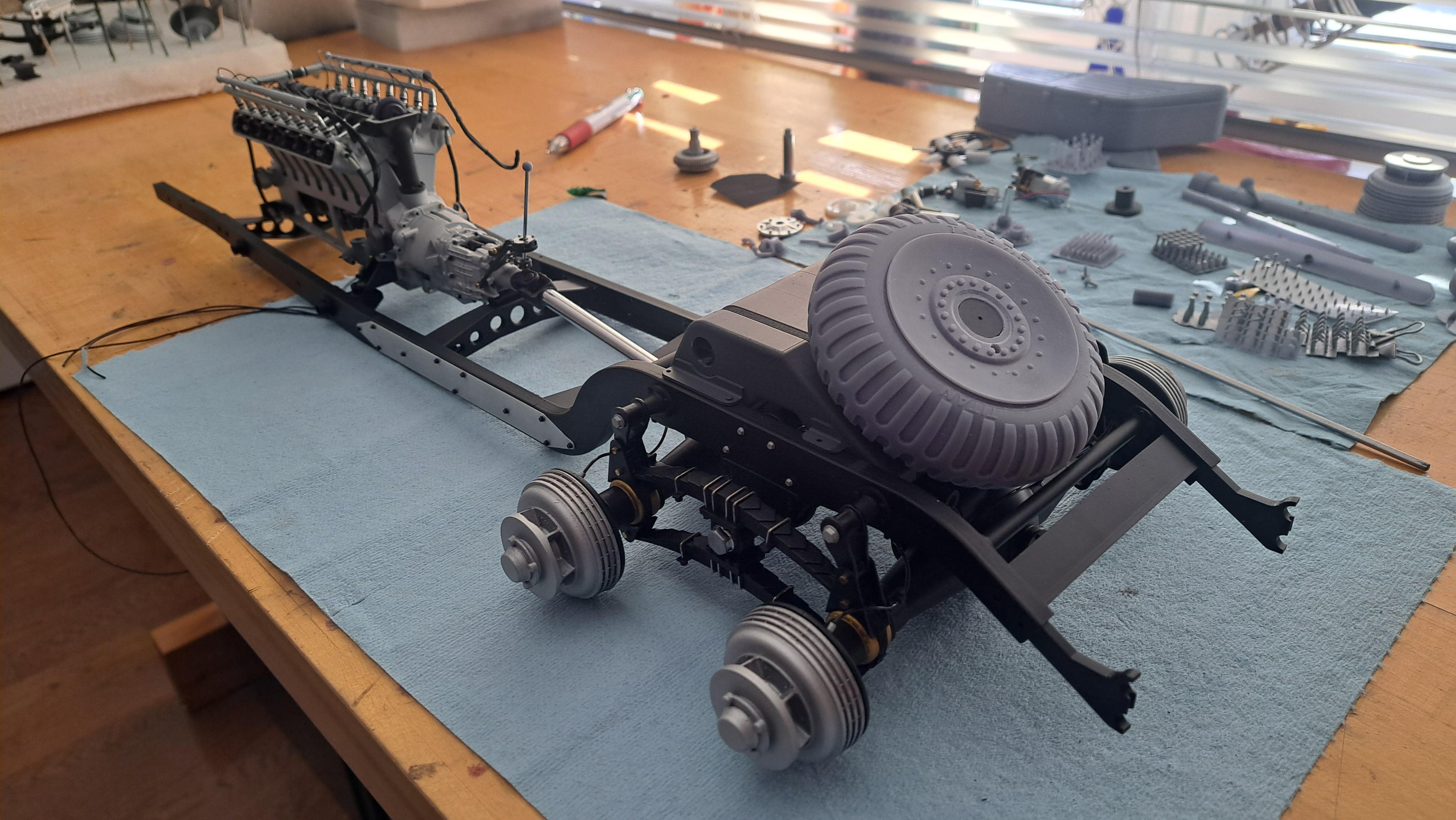
Engine and firewall bolted in for good. The dashboard is completed and installed but was still quite difficult do to despite it's simplicity (espacialy when compared to the Bentley's). All firewall related wiring and piping done. I'll be installing a fuel pump (stolen from the Bentley's spare parts bin) complete with feed hoses from the tank and outlet hoses to carburators. Next up, installing the head lights and wires. All wires from the head lights, gearmotor and tail lights will be routed towards the rear and eventually be hooked up to a multi pin connector that will be plugged into a control panel "a la" Marvel. Then, front and rear bumper and I'll need to design a stand of some sort to take the weight off the wheels, it's getting pretty heavy and I want to better distribute the weight on the frame.
-
Marvel's Hydra coupe 1/12 scale full scratch build
François replied to François's topic in WIP: Model Cars
The wheels and tires are all done. That mean I now have a rolling chassis, althought not 100% completed yet. I still need to finish the dashboard, head lights and a few other odds and ends before tackling the body. But I have to say, it's starting to look like an actual car and more and more like the design I made. 20250405_191053.mp4
-
Marvel's Hydra coupe 1/12 scale full scratch build
François replied to François's topic in WIP: Model Cars
Thanks Mattilacken, I've never tried the Vallejo rubber. The tamiya does à nice job once dried. -
Marvel's Hydra coupe 1/12 scale full scratch build
François replied to François's topic in WIP: Model Cars
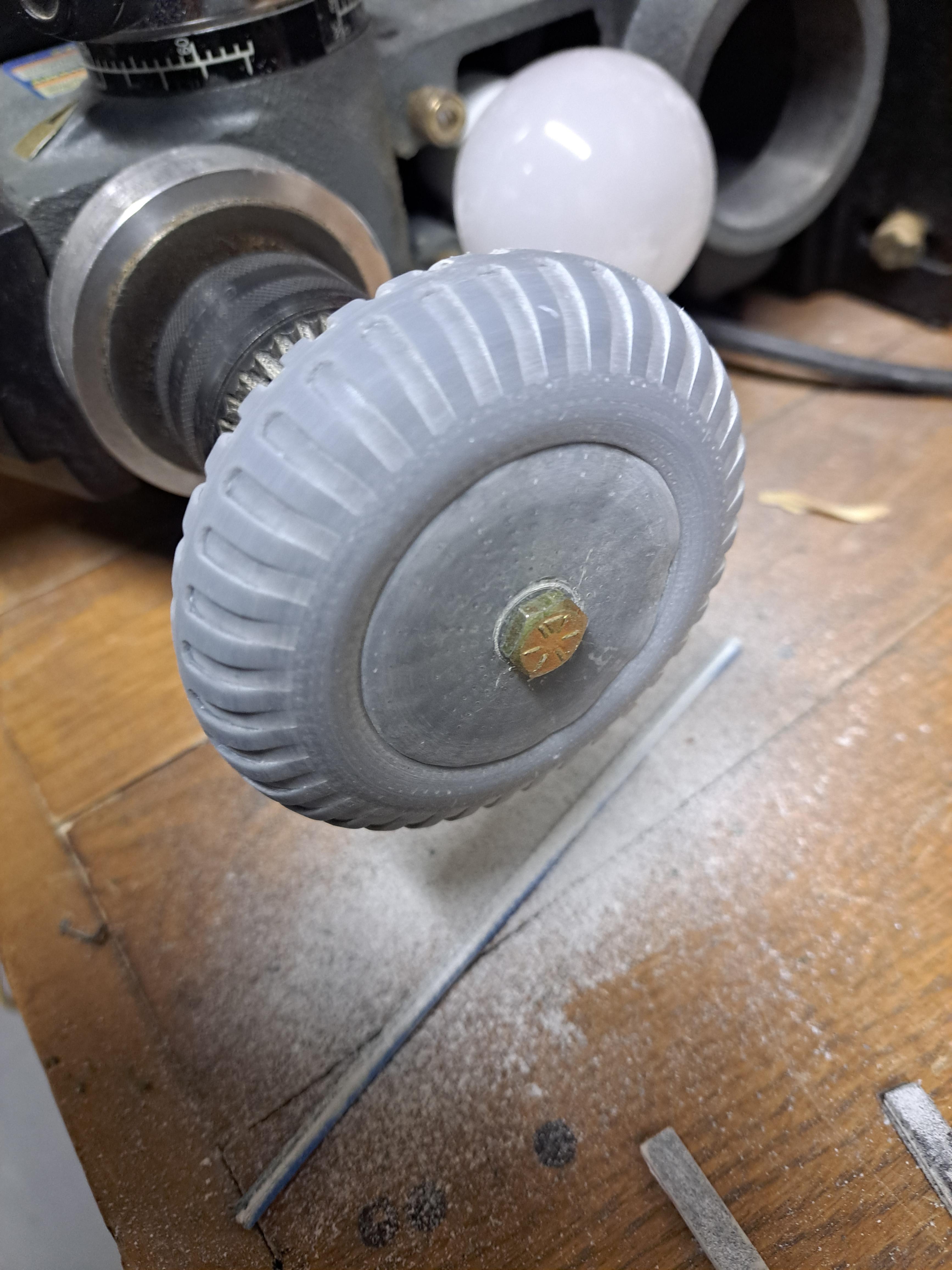
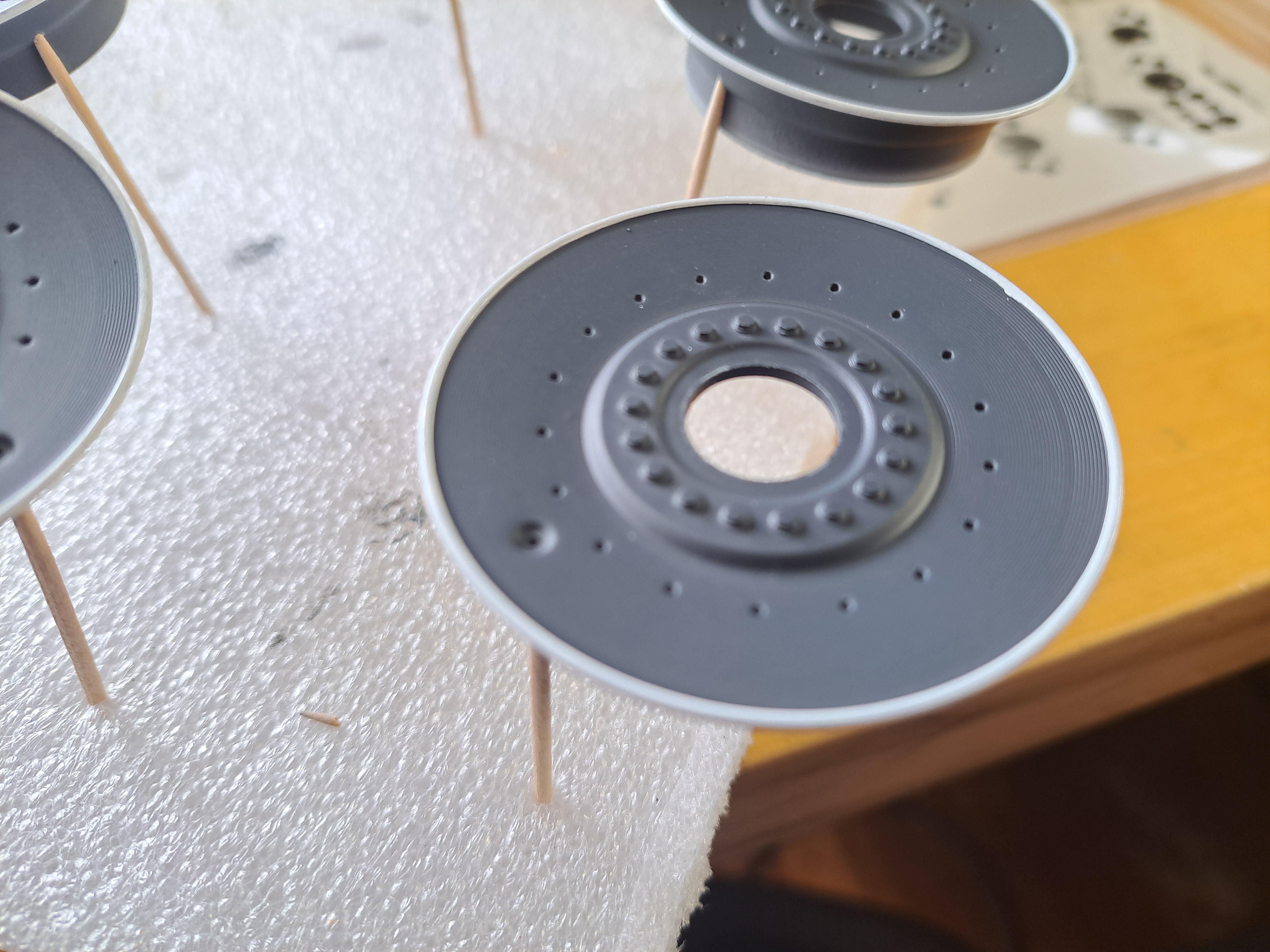
Almost done with the wheels and tires. All 7 wheels have been primed, painted and clear coated. Once dry, I'll install 18 white rivets per wheel and 1 valve. I've got 6 tires printed so far and 3 primed and painted. I decided to forgo the flexible resin and print the tires wirh my usual hard resin. The finished model will be under glass so no one will be kicking the tires. I should have the 7 wheels assembled sometime next week. Here are a few pictures. A small setup on my laid down drill press to sand away the support marks from the back side of the tire. Pinstripping of the wheels Clear coated wheels and painted tires (the paint on the tires is still wet, I used the black rubber from tamiya which gives a nice rubber like finish)
-
Marvel's Hydra coupe 1/12 scale full scratch build
François replied to François's topic in WIP: Model Cars
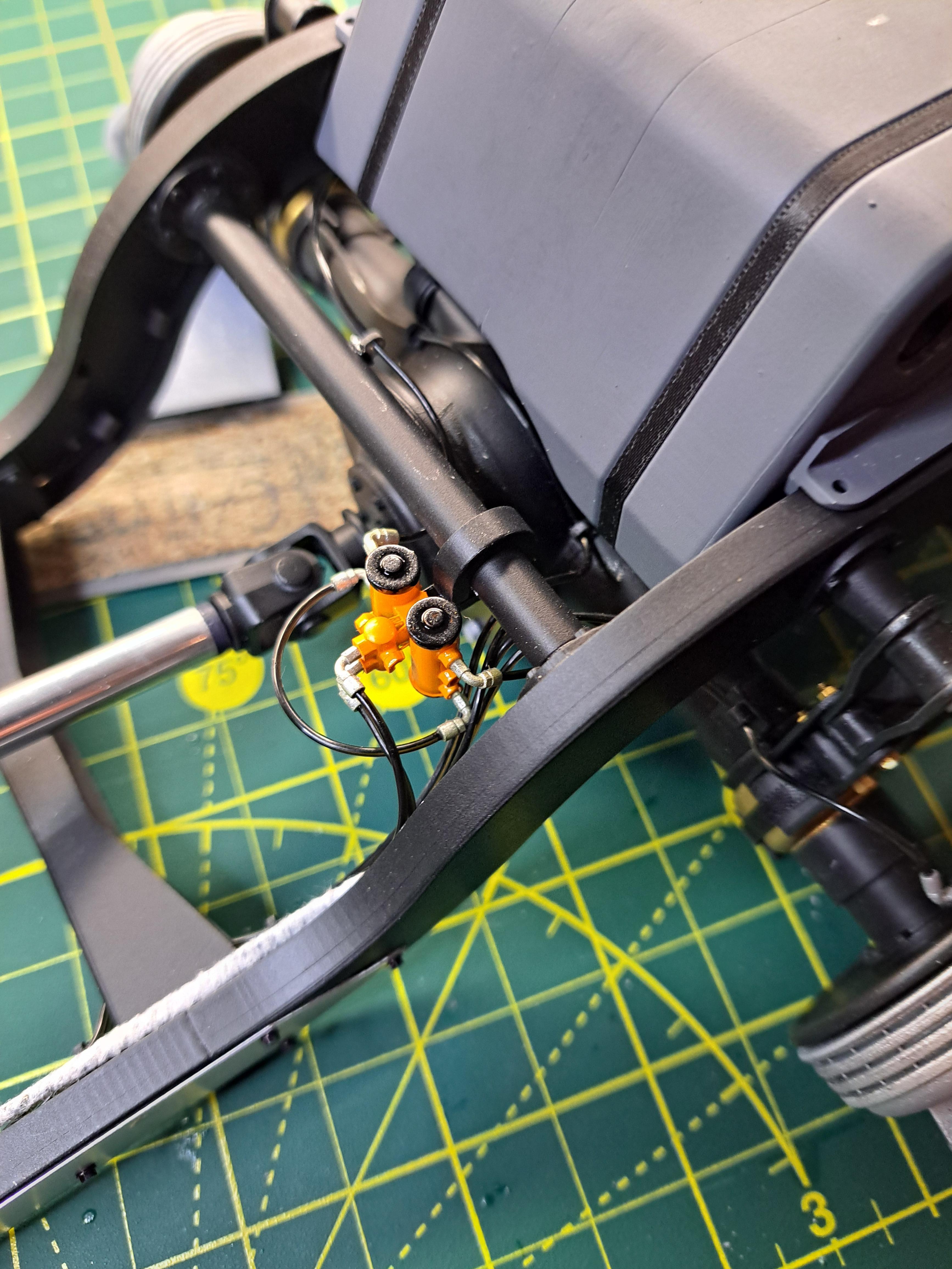
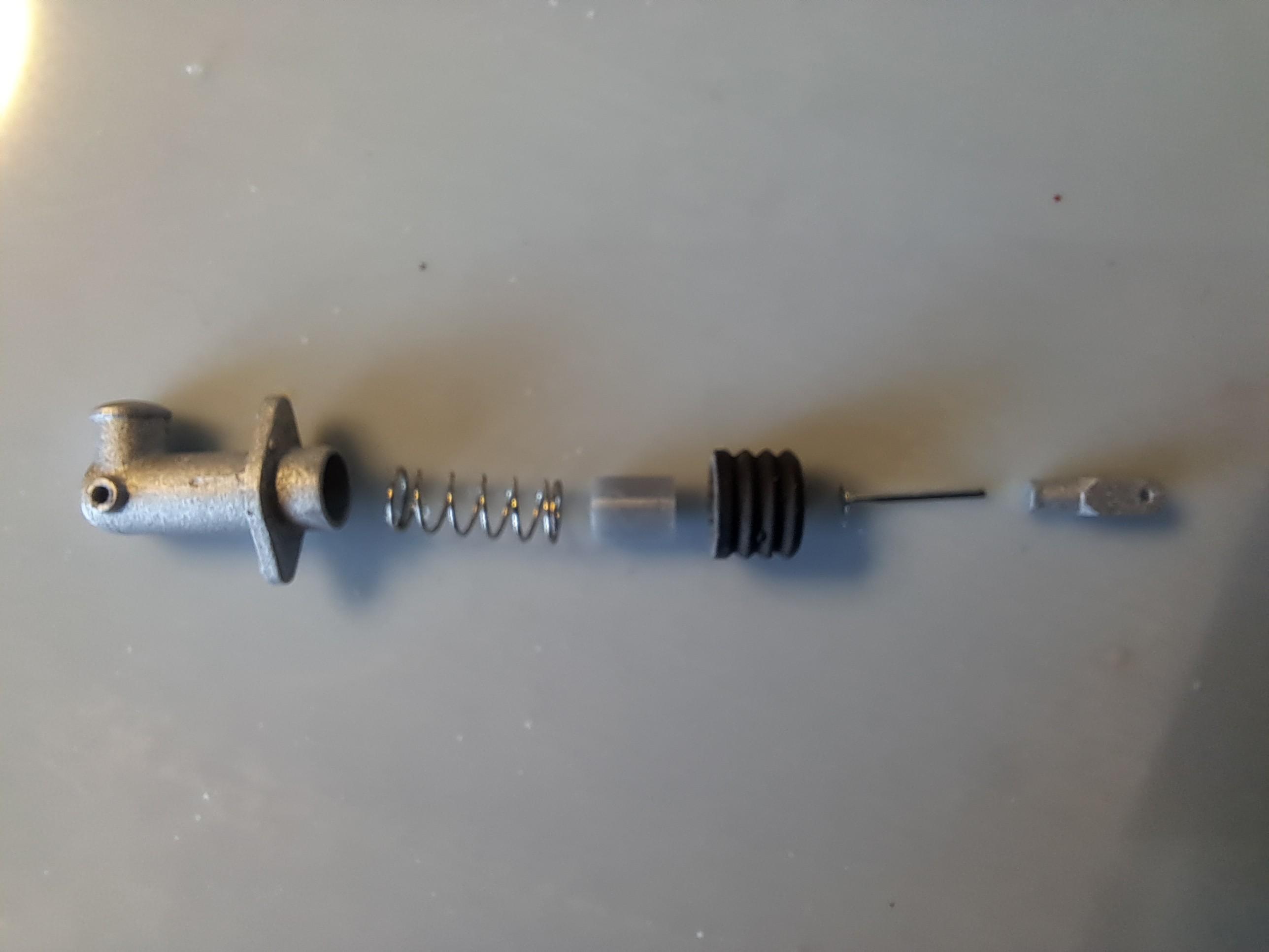
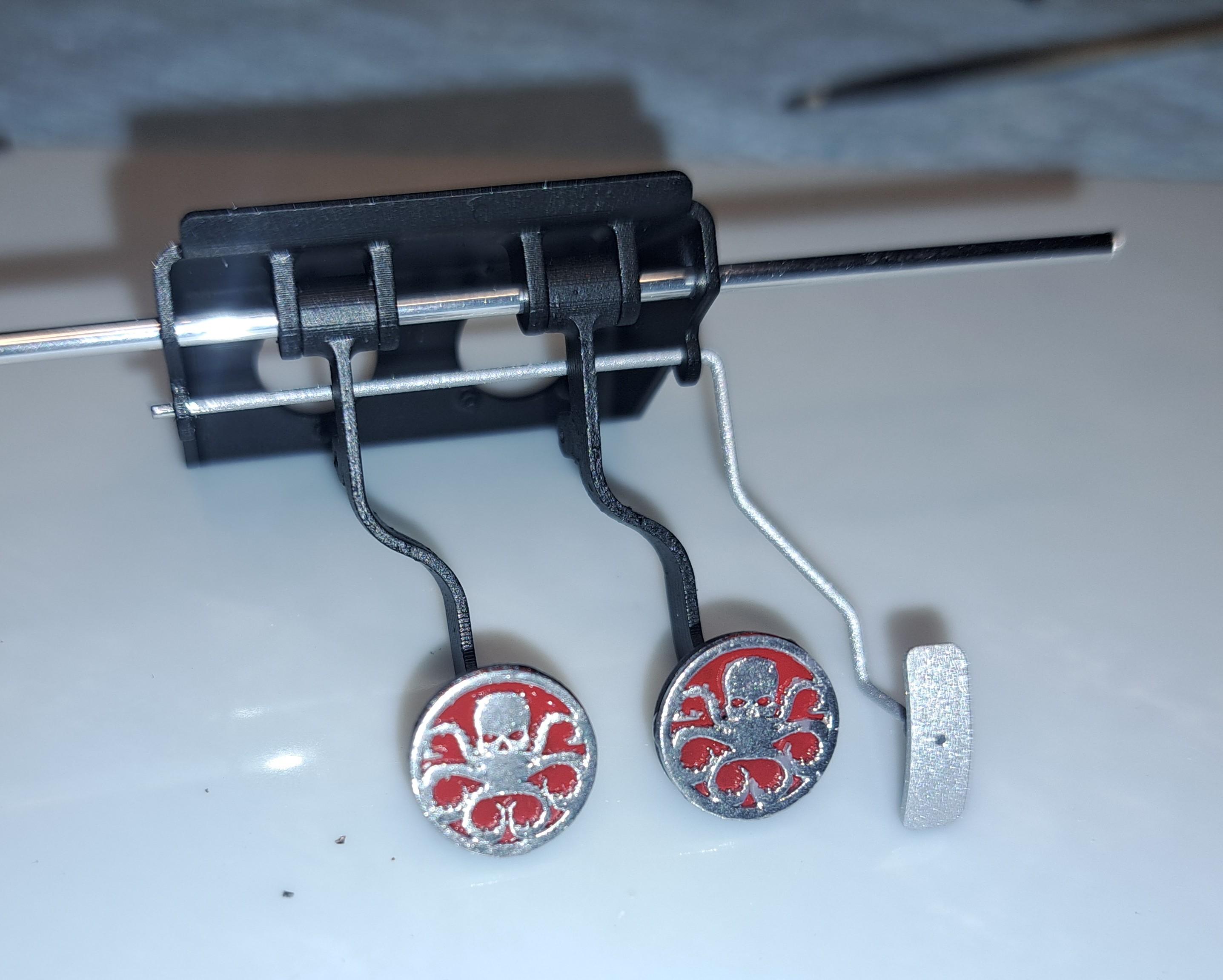
You know when you're too close to the forest you can't see the tree? I've been working with the steering mecanism for the last week but just found this problem today. (Hint, look at the rotation of the steering vs the rotation of the wheels) 20250330_213929.mp4 The problem is that I printed a left hand worm instead of a right hand. I've reprinted the steering column parts with the correct worm so easy fix. I test fitted the dash board, fits like it should but I don't like tge dial gage area Newly redesign dashboard with a test dial in place. Exploded views of the clutch master assembly And assembled Brake and clutch masters in place on firewall with brake piping done Pedal box completed and installed Functional brake and clutch pedals 20250330_202844~2.mp4
-
Marvel's Hydra coupe 1/12 scale full scratch build
François replied to François's topic in WIP: Model Cars
You know the saying that goes 'one step forward 2 steps back'? Well that's exactly what happenned with the head lights. I had 1 completly installed but I wasn't bright enough to test the lighting before gluing everything in place. It turns out that the light from the bulb shines thru the bucket wall, which is only .040" thick and even though it's chromed. So I had to remove it by breaking the mounting bracket. I took the opportunity the redo the chrome on all 4 buckets since I didn't like how it looked so that's a plus. I also printed a heavy wall bucket liner that I painted black on the outside and silver on the inside. Now, the light goes out only by the front of the bucket as should be. Bucket without liner (this bucket is not chromed so the efect is worse) Bucket with liner inside, problem solved The heavy wall liner And liner in bucket On the plus side of my Hydra day, all the firewall parts are painted and I started the pedal box assembly. The hydra logo on the brake and clutch are kinda cool! If all goes to plan, I should have working pedals once hooked up to the spring loaded clutch and brake masters.
-
Marvel's Hydra coupe 1/12 scale full scratch build
François replied to François's topic in WIP: Model Cars
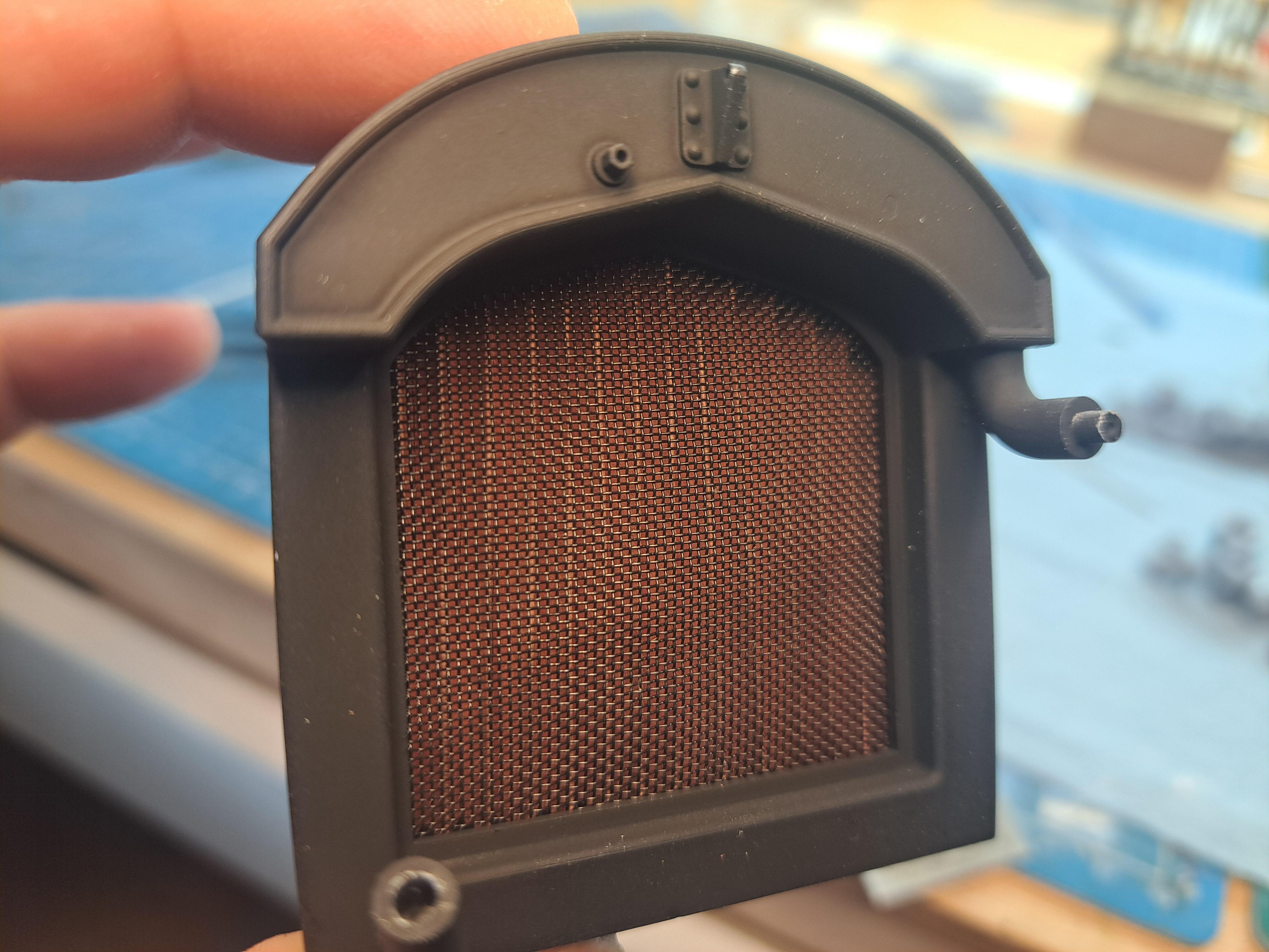
A lot was done today. I printed all the parts for the firewall assembly and they are ready for paint. I test fitted the firewall on the frame and it fit perfectly. I test printed the steering wheel, first print not perfect but the second should be good. I completed the radiator core with a fine wiremesh and pleated core. I threaded the gearmotor leads thru a rubber hose to hide them and started to install the head lights. Unfortunately, I scratched one of the head light bucket so I had to rechrome it. I'll have to wait a couple of weeks before installing it. Firewall parts ready for paint Test fitting of firewall Steering wheel test print Completed radiator core Threading gearmotor leads First of 4 head lights installed
-
Marvel's Hydra coupe 1/12 scale full scratch build
François replied to François's topic in WIP: Model Cars
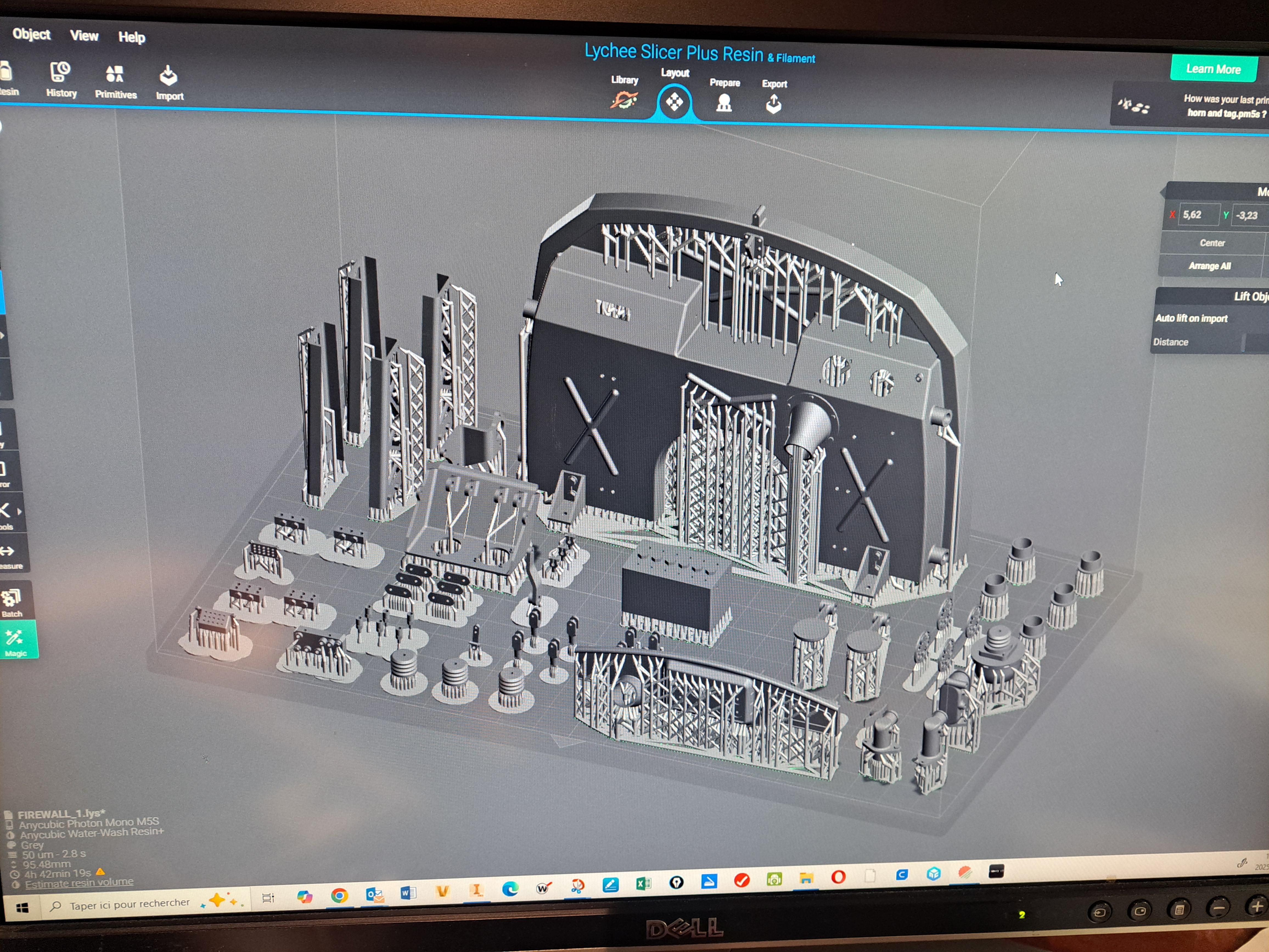
I'm starting work on the firewall assembly, all parts are being printed. Here's what the printer plate looks like.
-
Marvel's Hydra coupe 1/12 scale full scratch build
François replied to François's topic in WIP: Model Cars
Thank you Cody! I very much enjoying this build, glad to see orhers are too. -
Marvel's Hydra coupe 1/12 scale full scratch build
François replied to François's topic in WIP: Model Cars
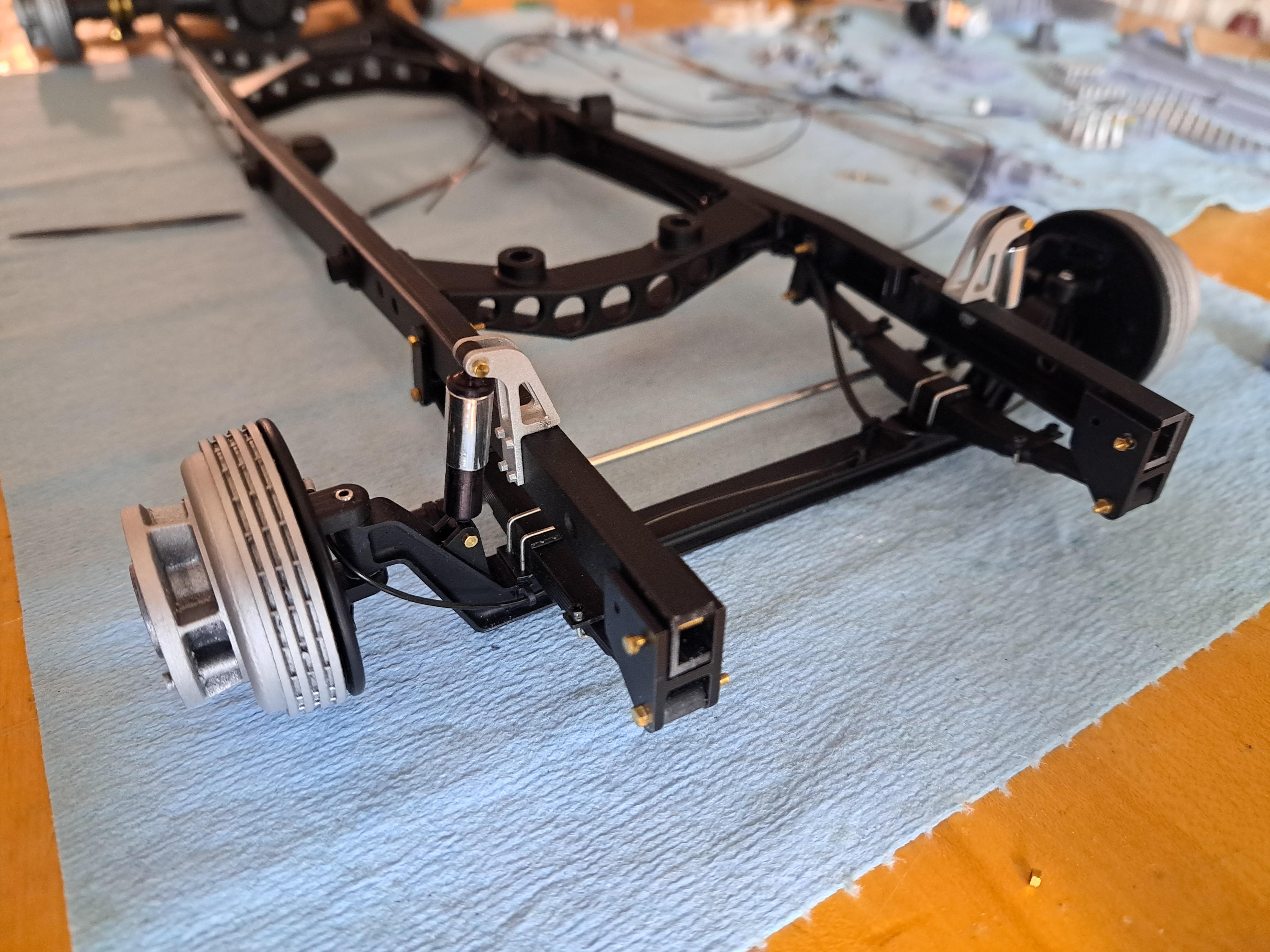
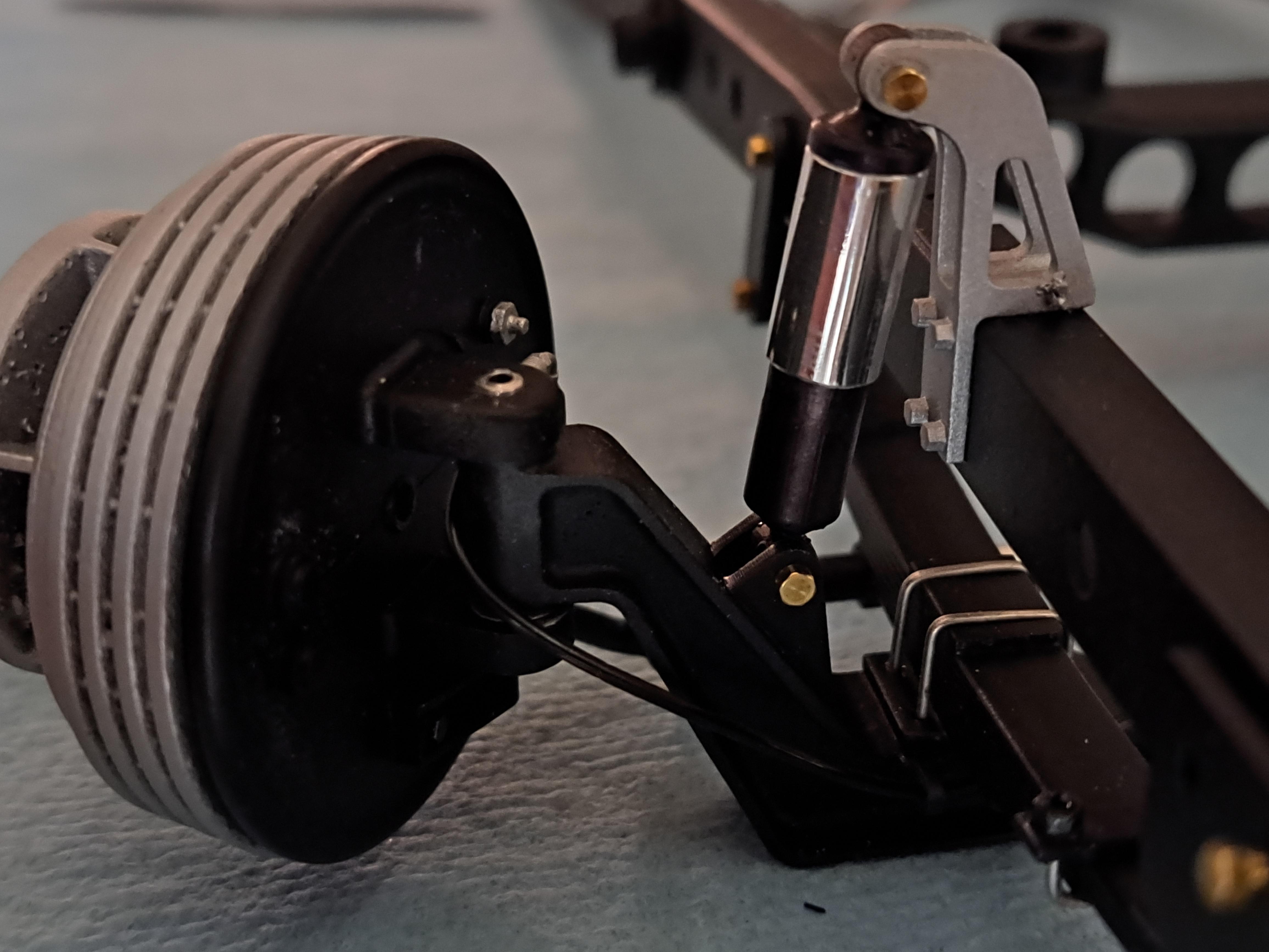
I finished the front suspension installation. Brake line are in and the steering works. I also test fitted the radiator, the blower top cover has the final paint color, looks pretty good. 20250323_201805.mp4
-
Marvel's Hydra coupe 1/12 scale full scratch build
François replied to François's topic in WIP: Model Cars
The wheels are printed, I test tried them on just gor fun and to see if it rolls... it rolls. 20250316_140322.mp4 (sorry for the poor picture quality)
-
Marvel's Hydra coupe 1/12 scale full scratch build
François replied to François's topic in WIP: Model Cars
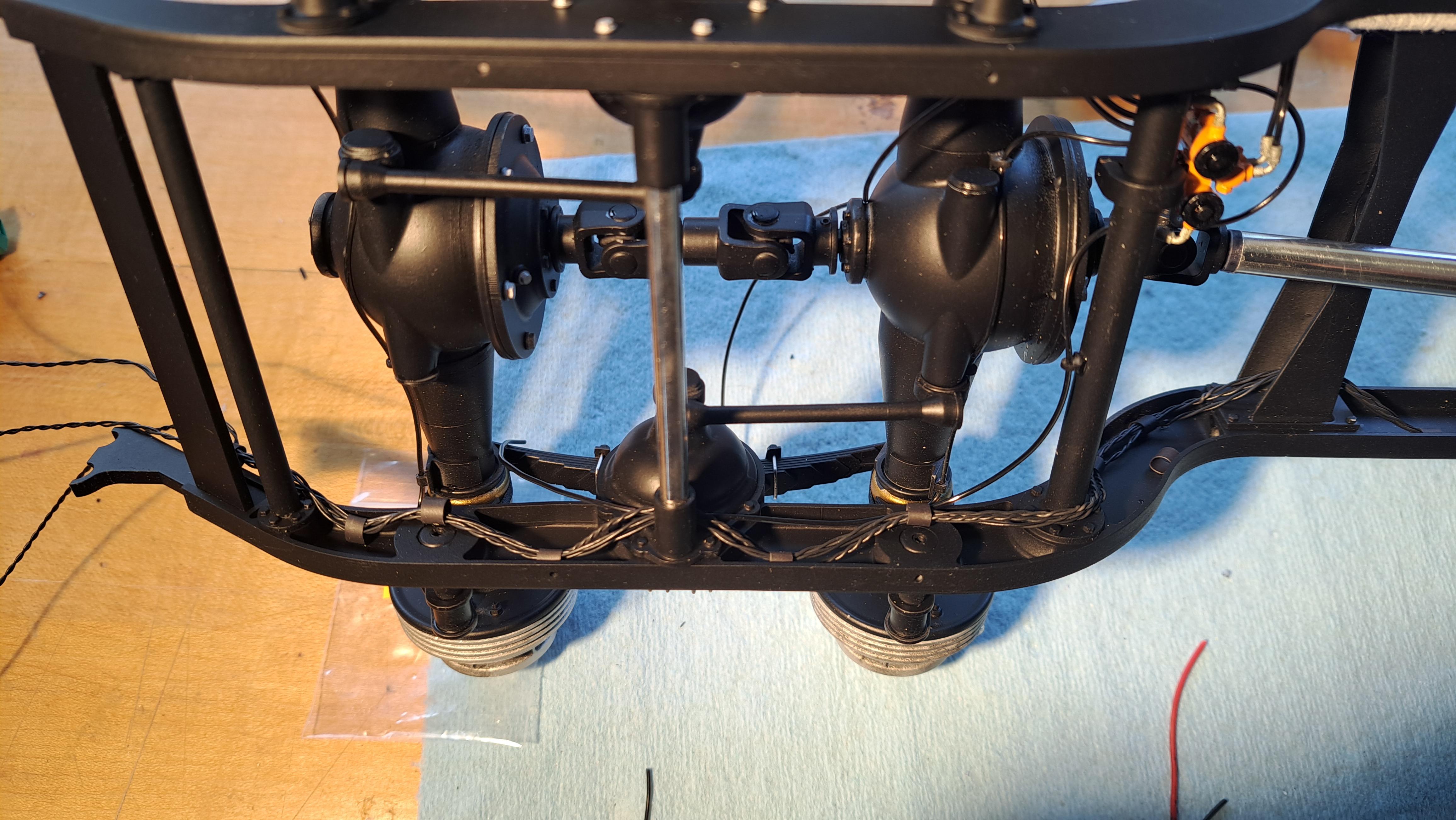
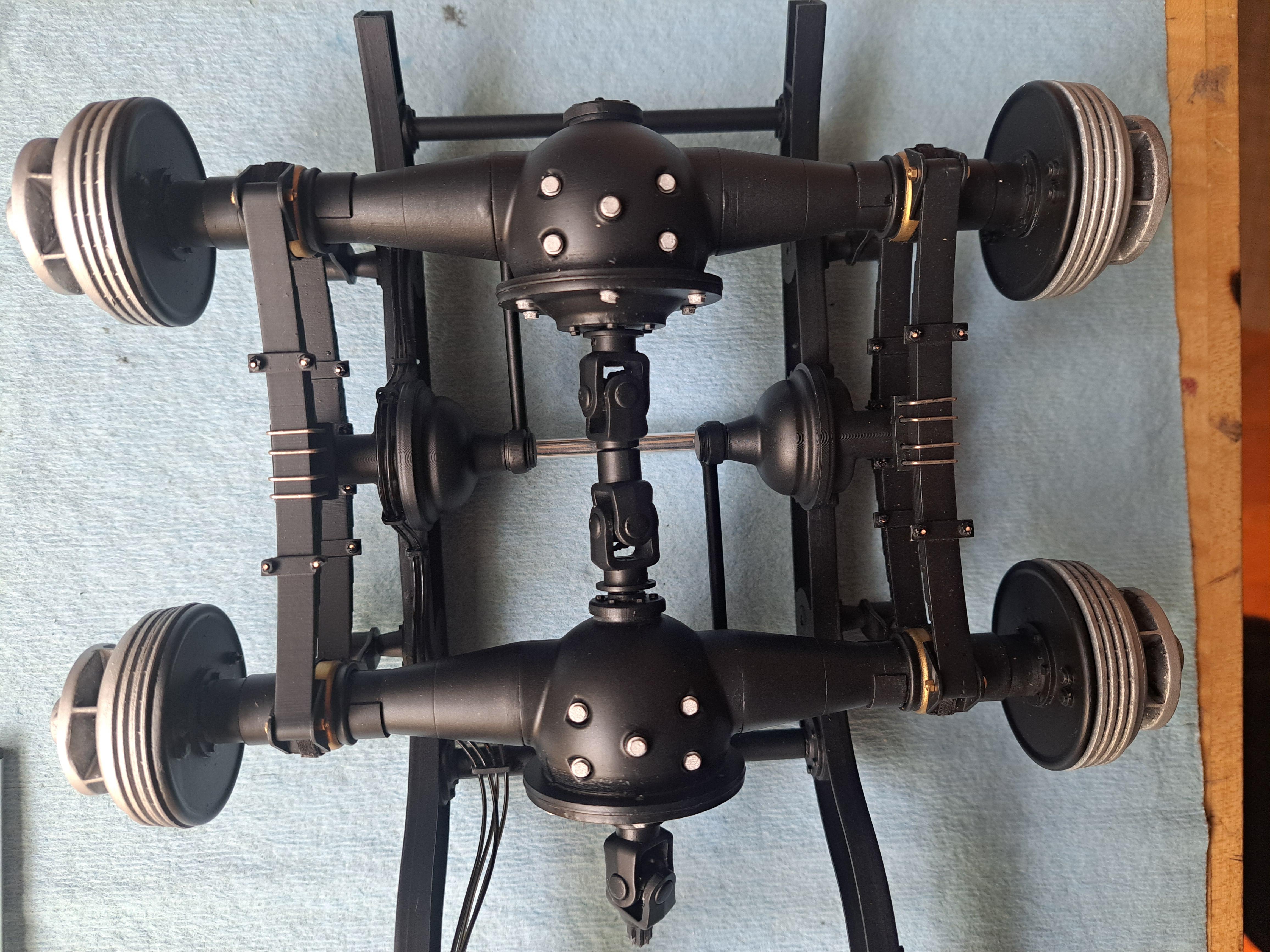
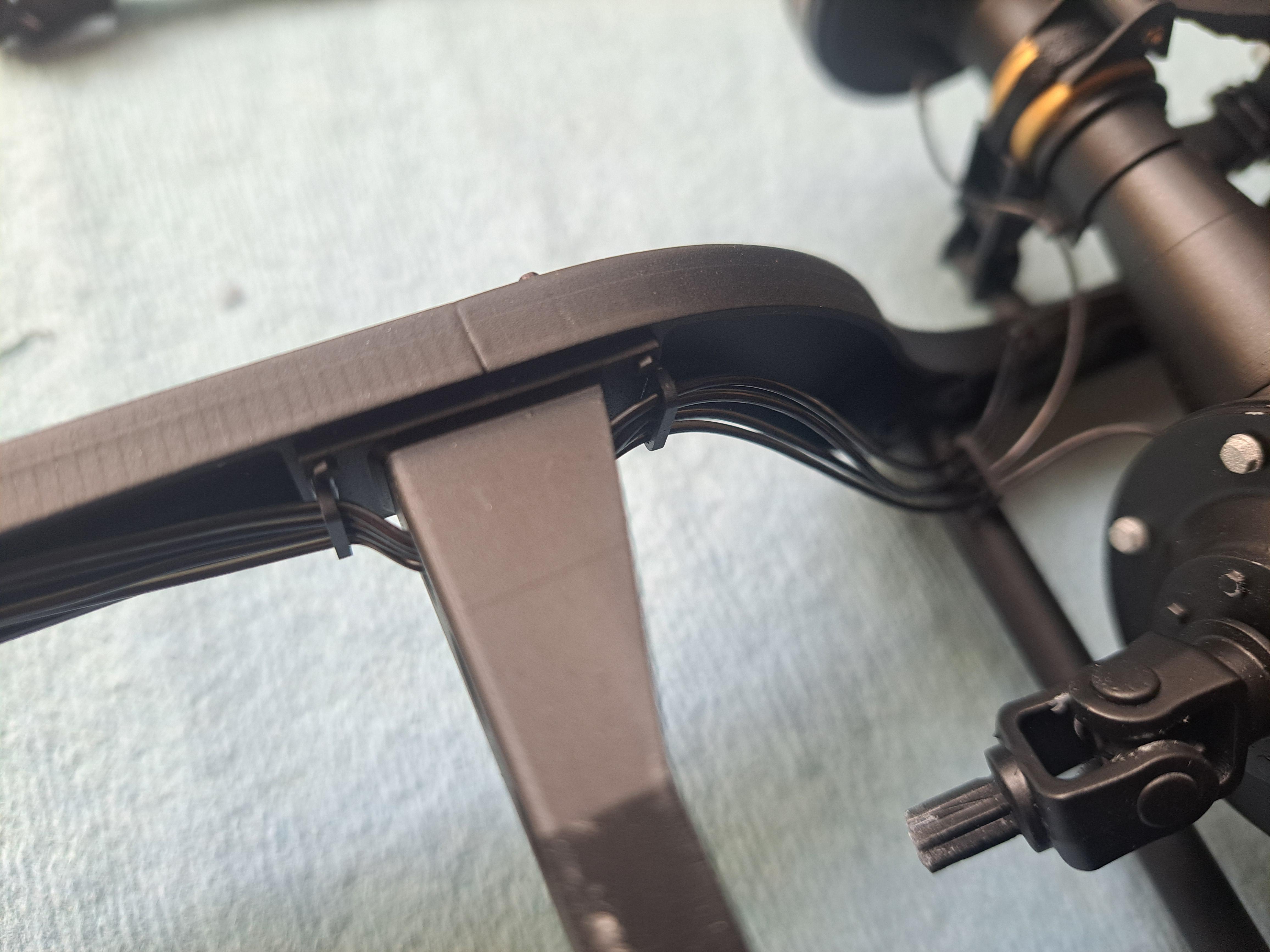
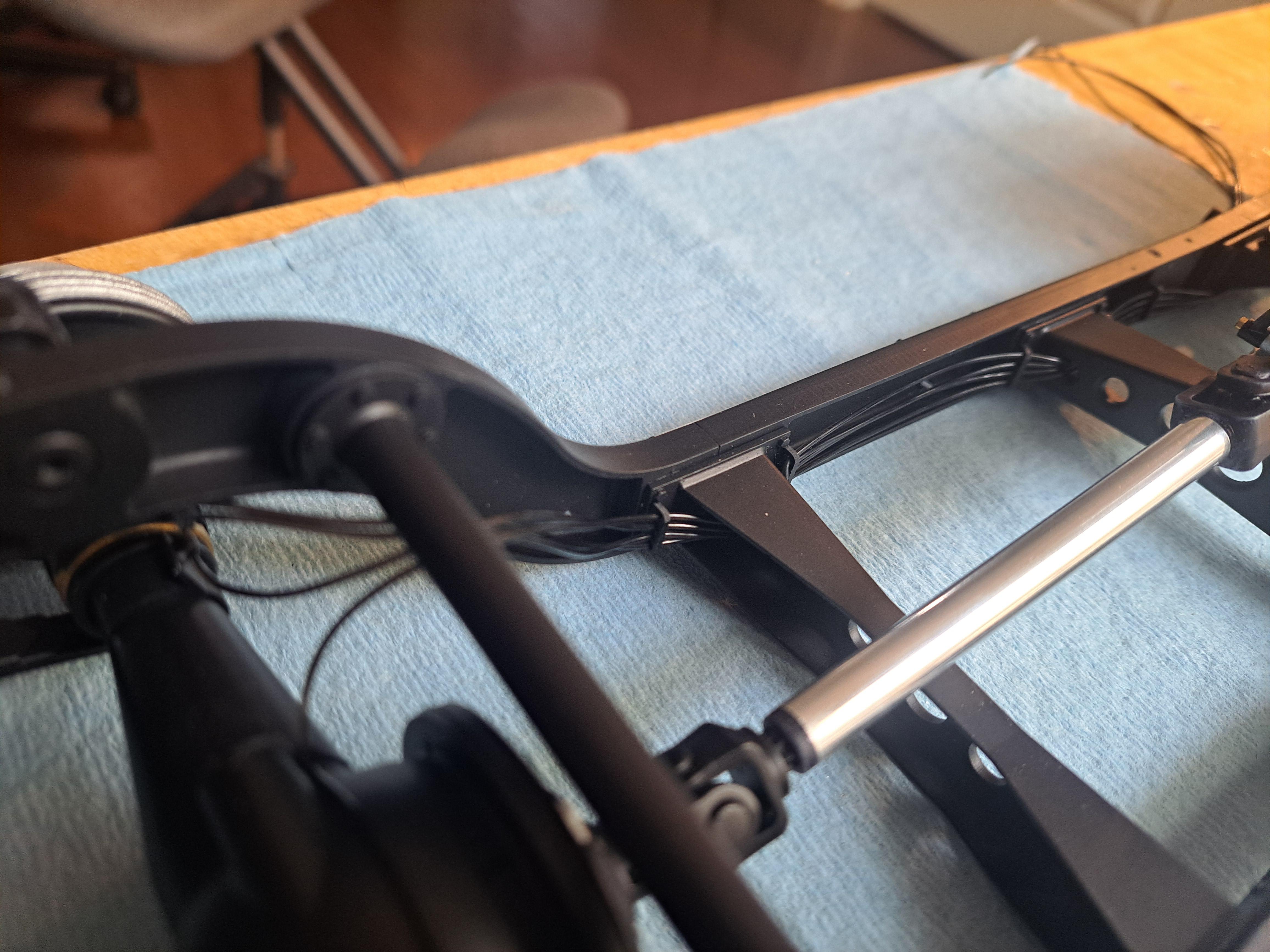
The rear end is all done and I'm very pleased with the way everything went together easily. Next step, the front end. Viewed from under Some brake line routing
-
Marvel's Hydra coupe 1/12 scale full scratch build
François replied to François's topic in WIP: Model Cars
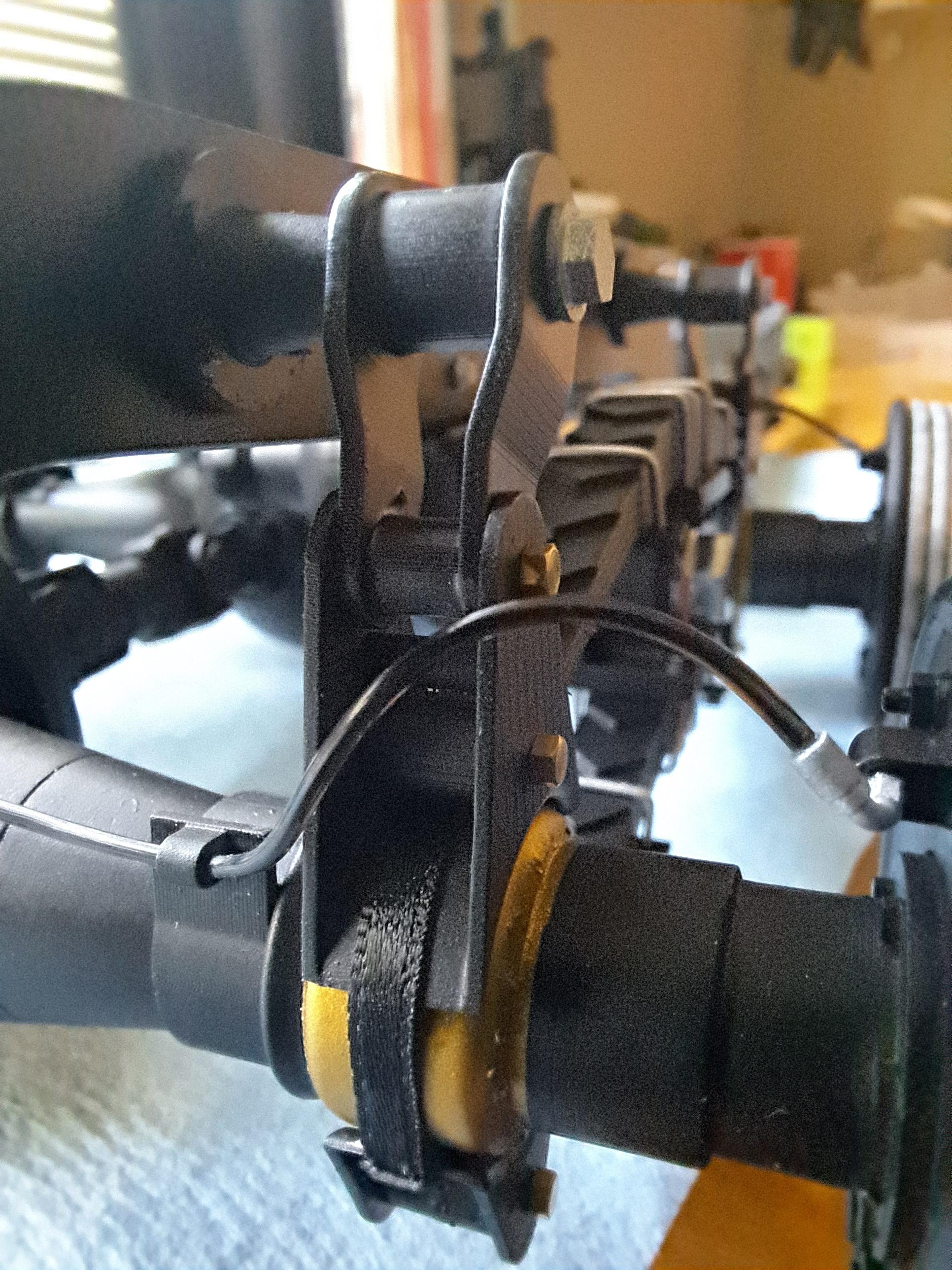
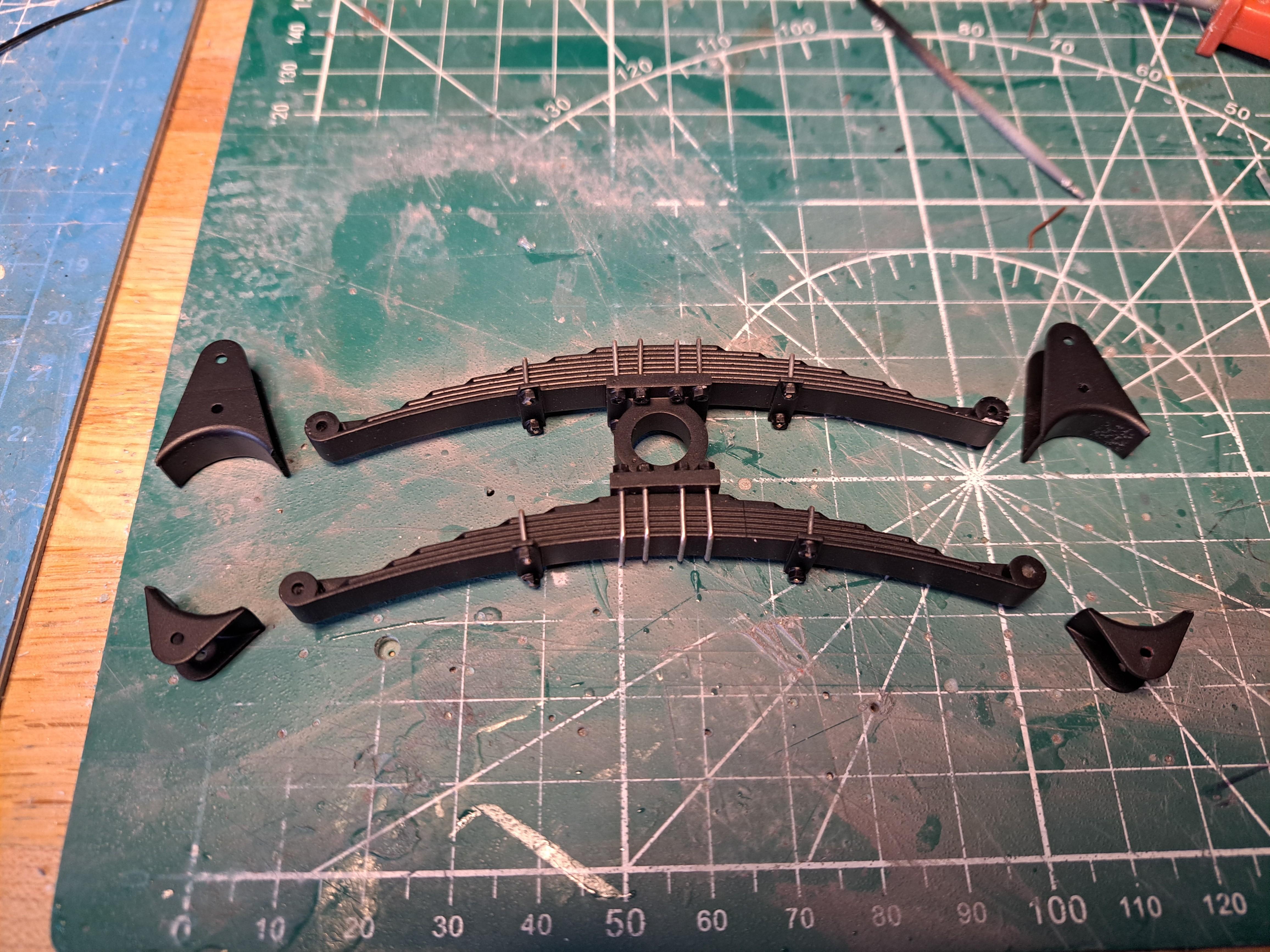
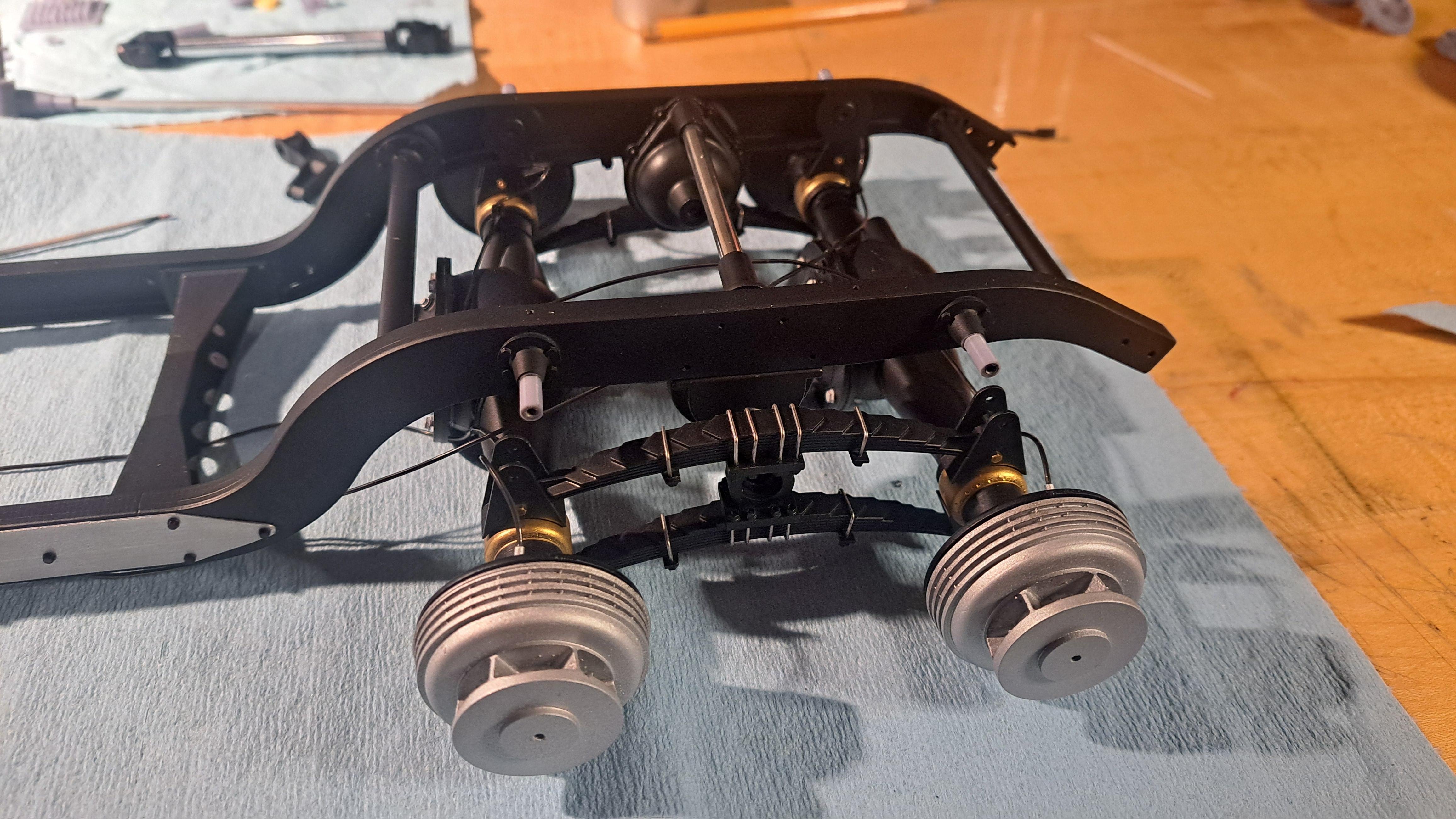
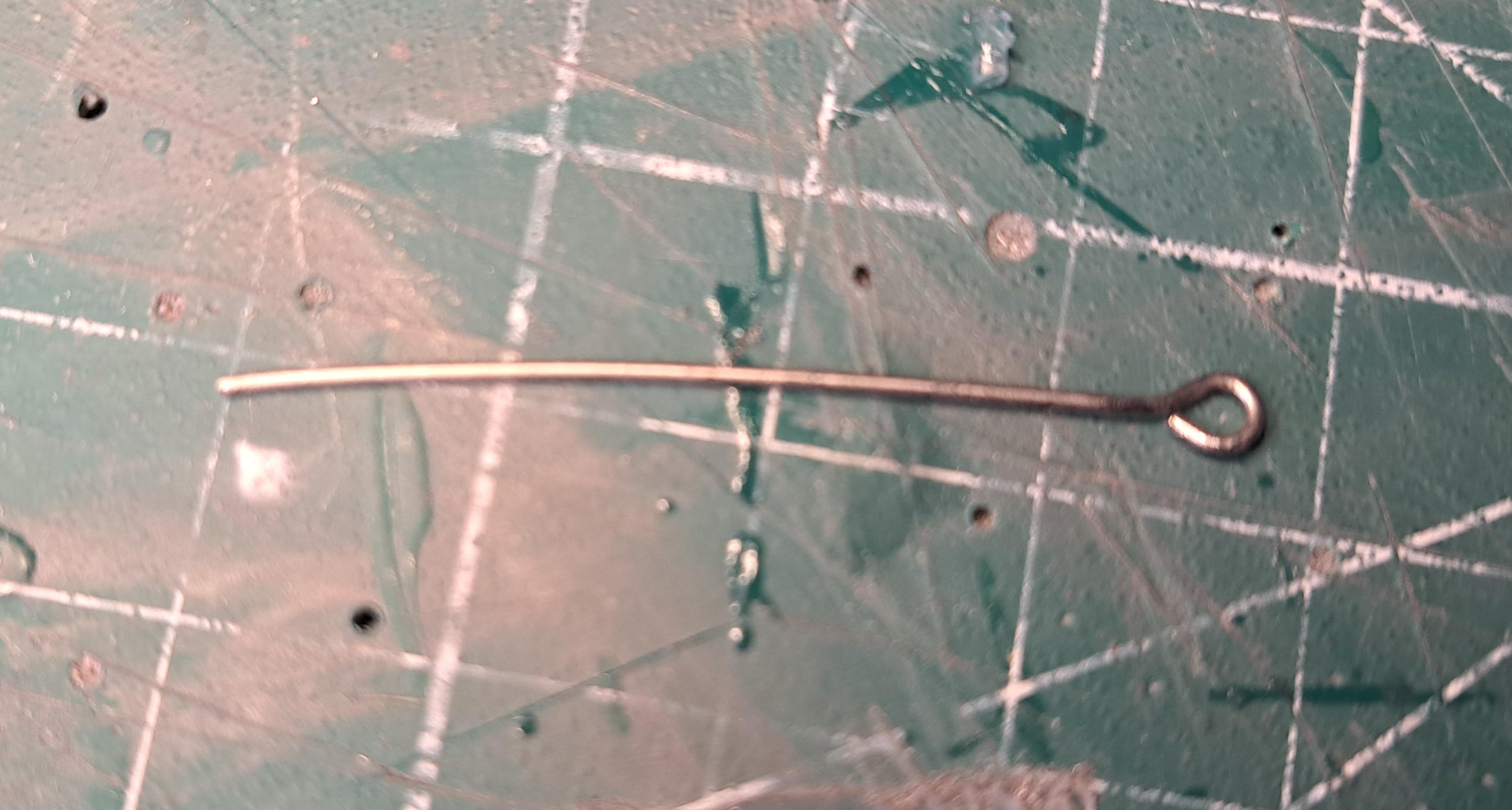
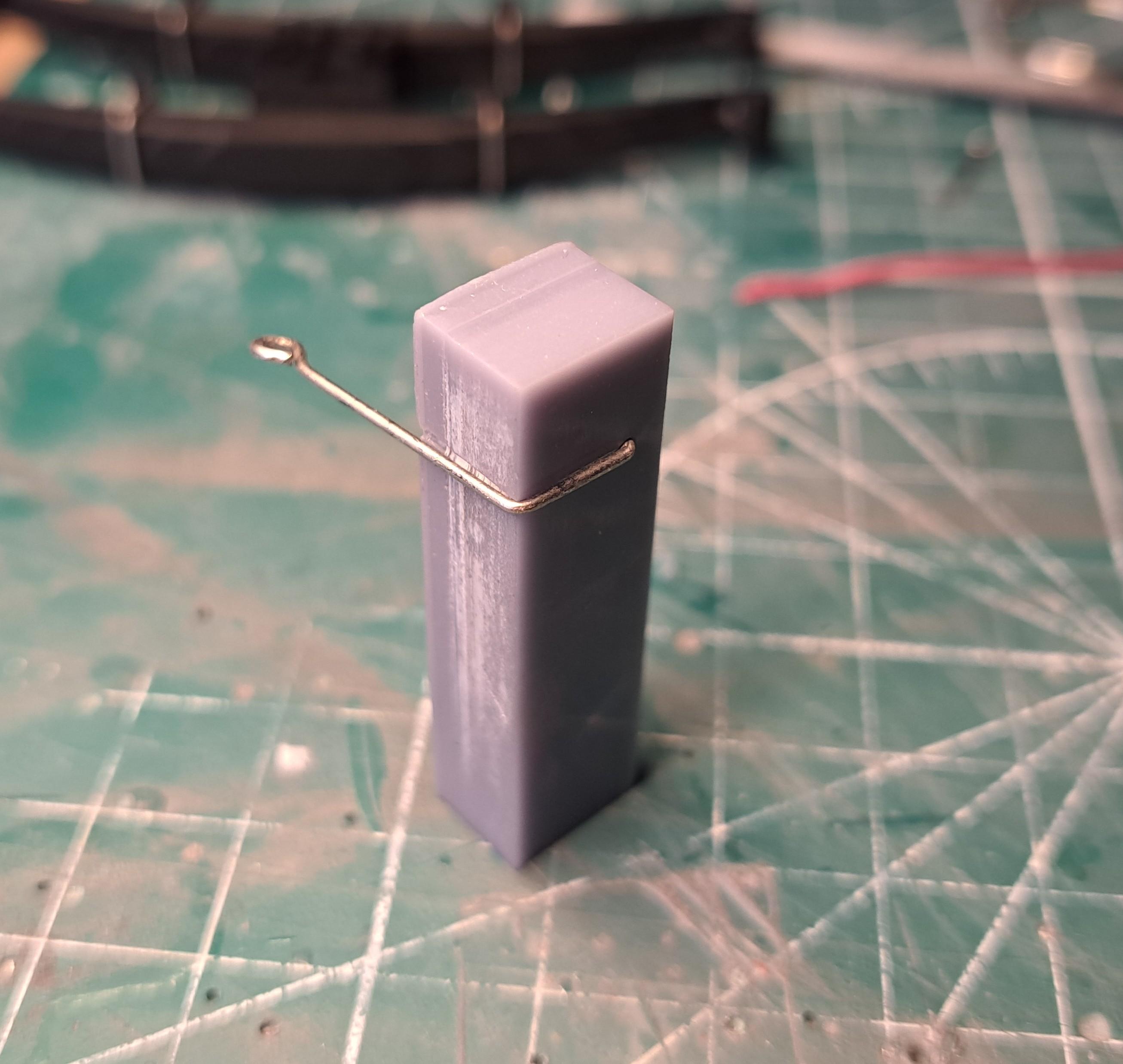
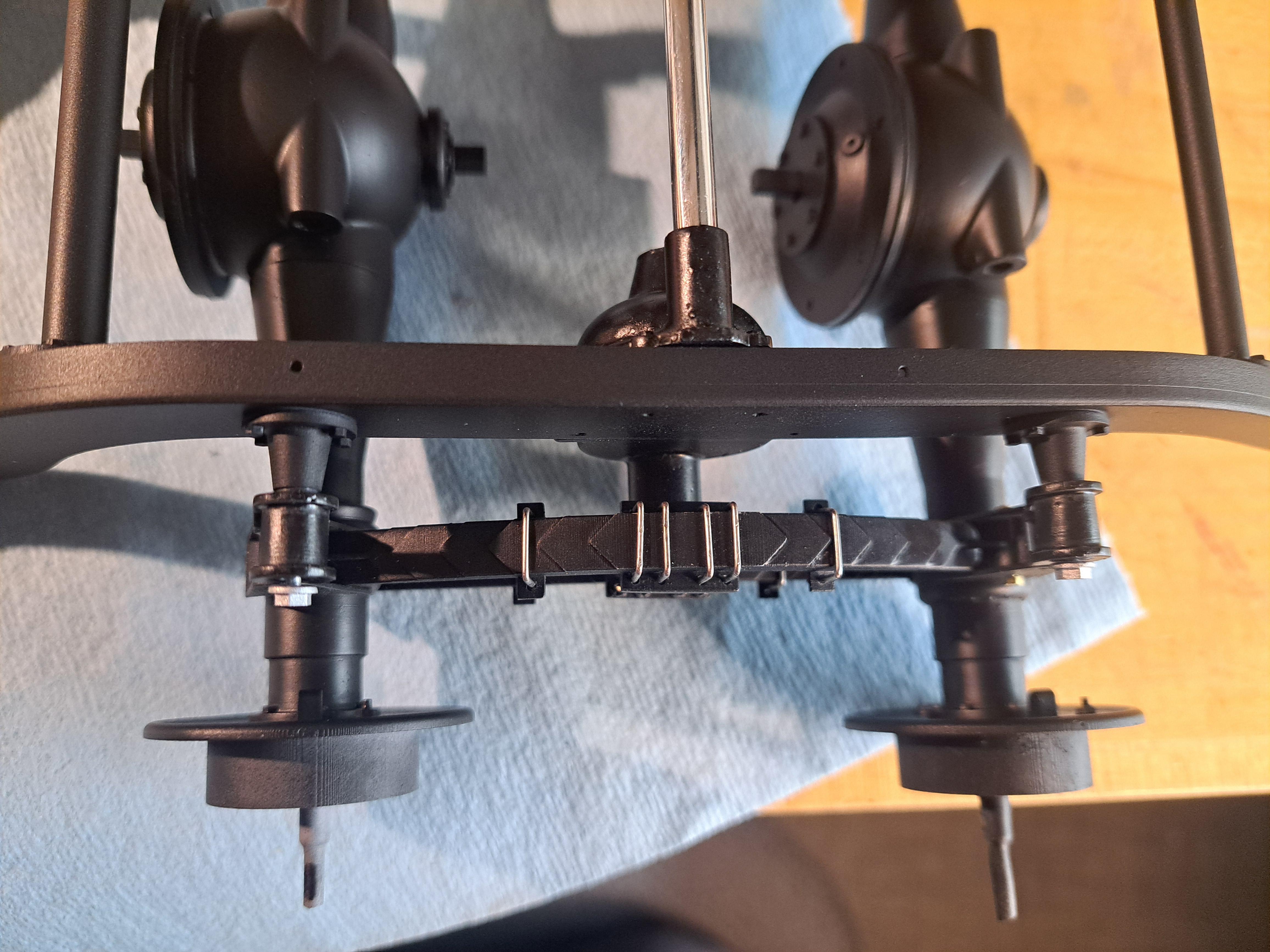
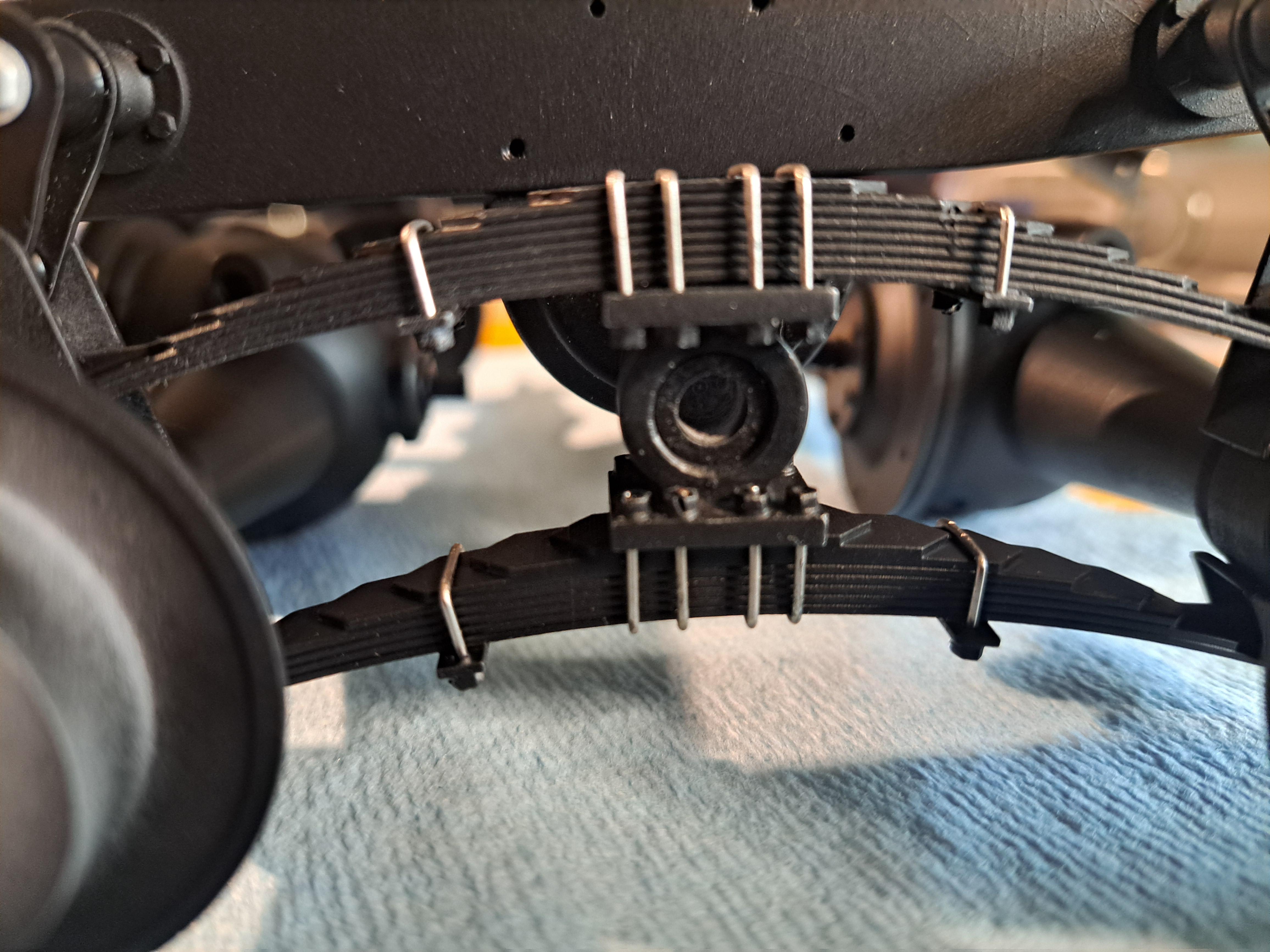
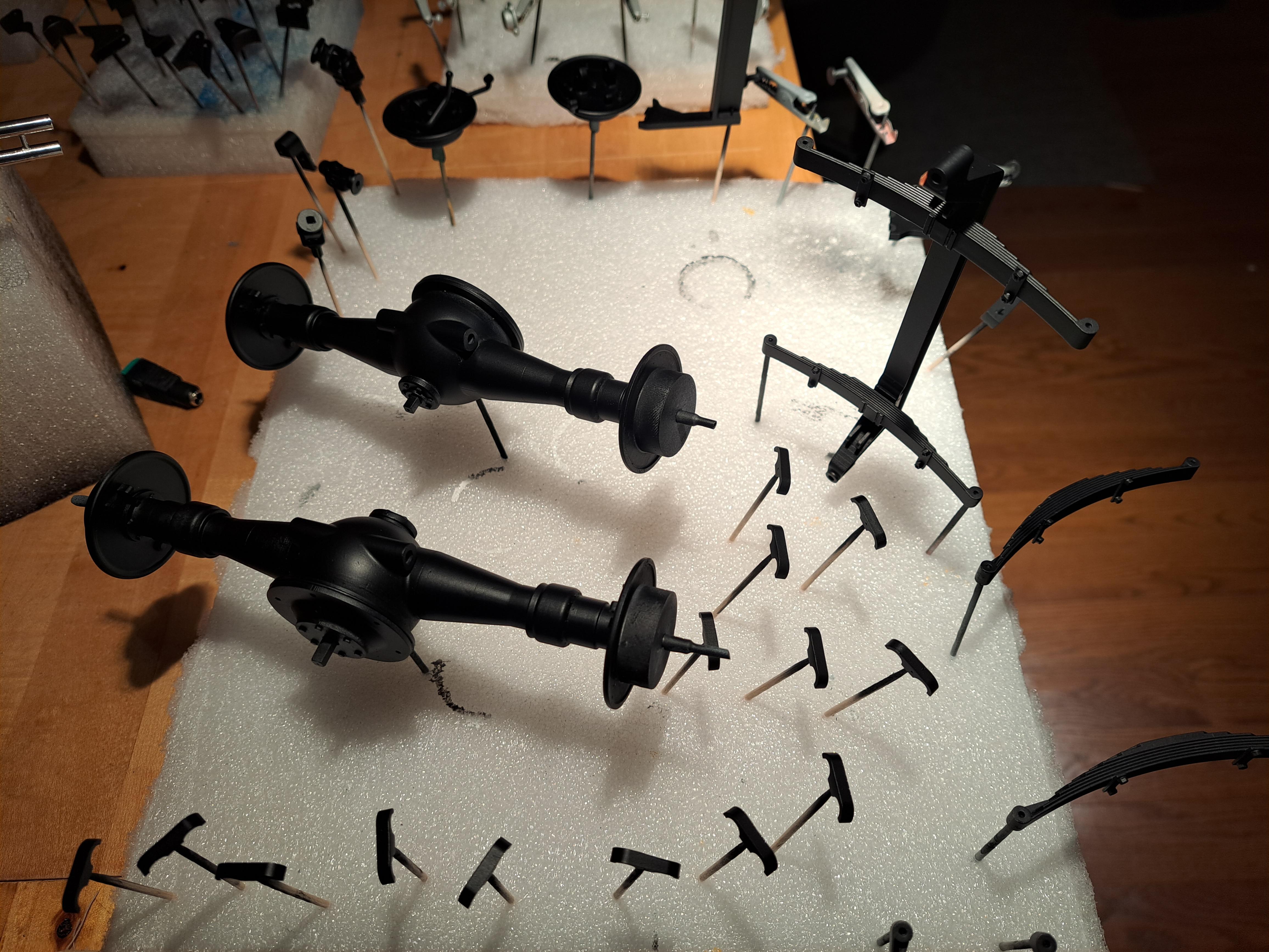
I finished all the ubolts for all the leafsprings assembly, here's how I proceded in order to get identical shapes. Raw material (cheap steel pin) inserted in bending jig After bending After trimming Finished rear leafspring I dry fitted the rear suspension with both rear axels, althought not easy to get in place, everything seems to fit perfectly. I installed the brake lines (black rubber hoses) that will eventualy be routed towards the firewall and brake booster. Similar lines will also come from the front brakes.
-
Marvel's Hydra coupe 1/12 scale full scratch build
François replied to François's topic in WIP: Model Cars
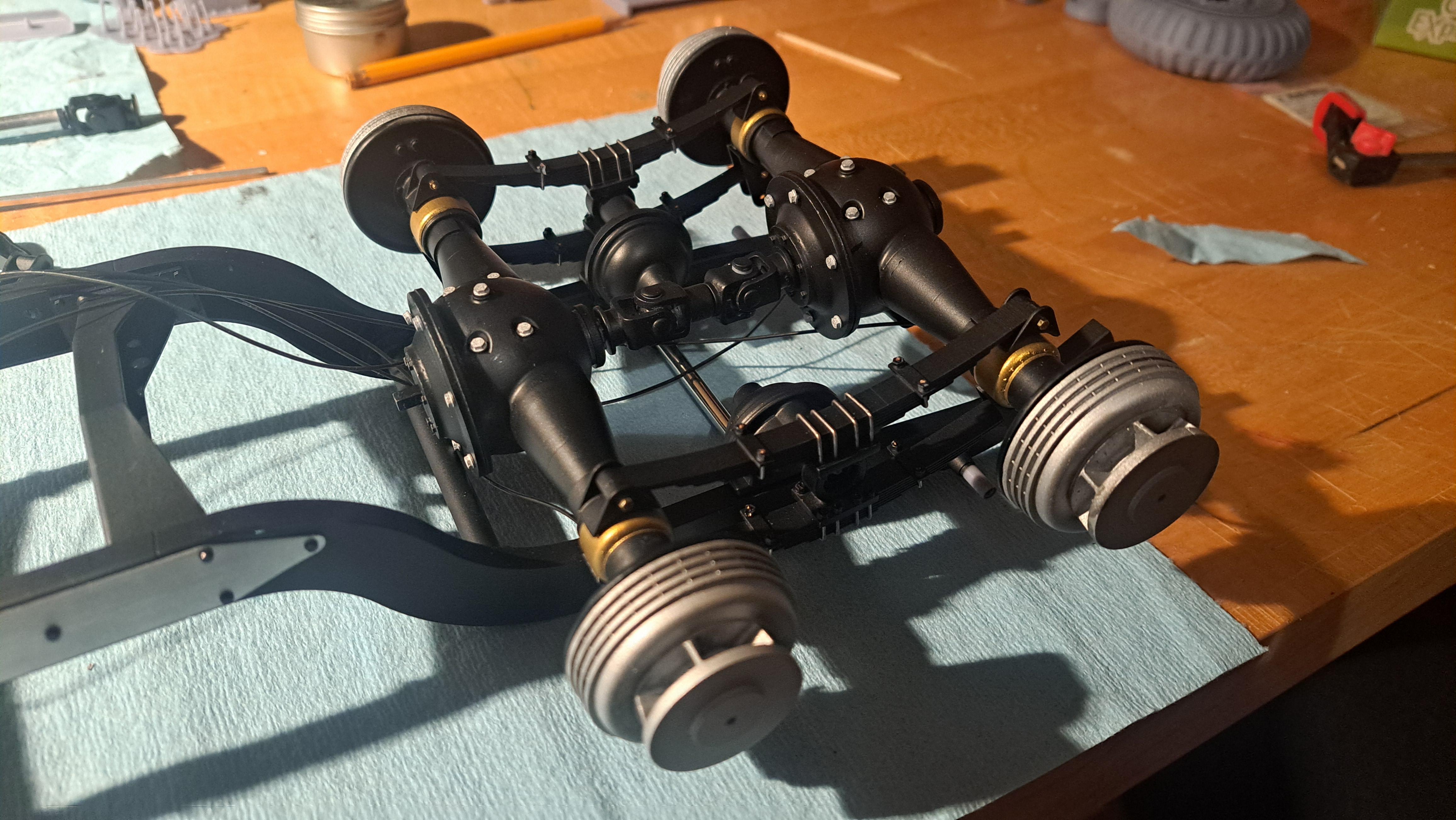
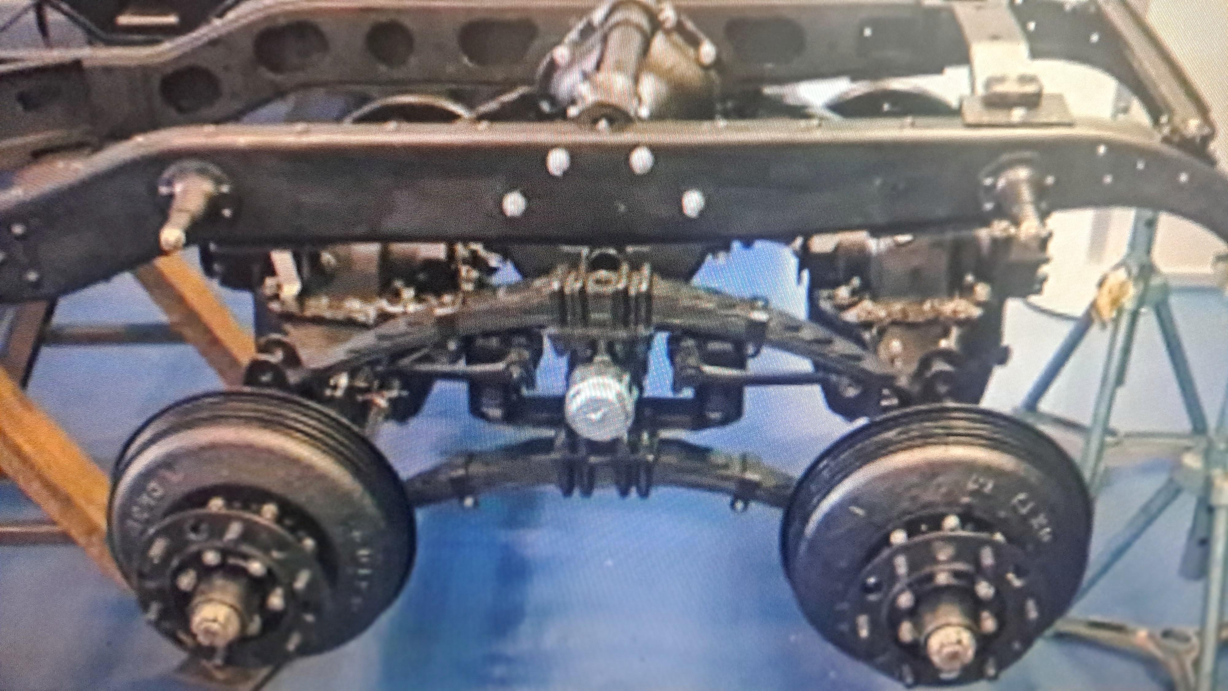
Did some assembly today. I worked on the rear suspension. It's going to be quite a puzzle to get all these parts assembled in the correct order but I think it should all fit nicely. As a reminder, here is the only reference I had for the rear suspension And here is my design And the result so far
-
Marvel's Hydra coupe 1/12 scale full scratch build
François replied to François's topic in WIP: Model Cars
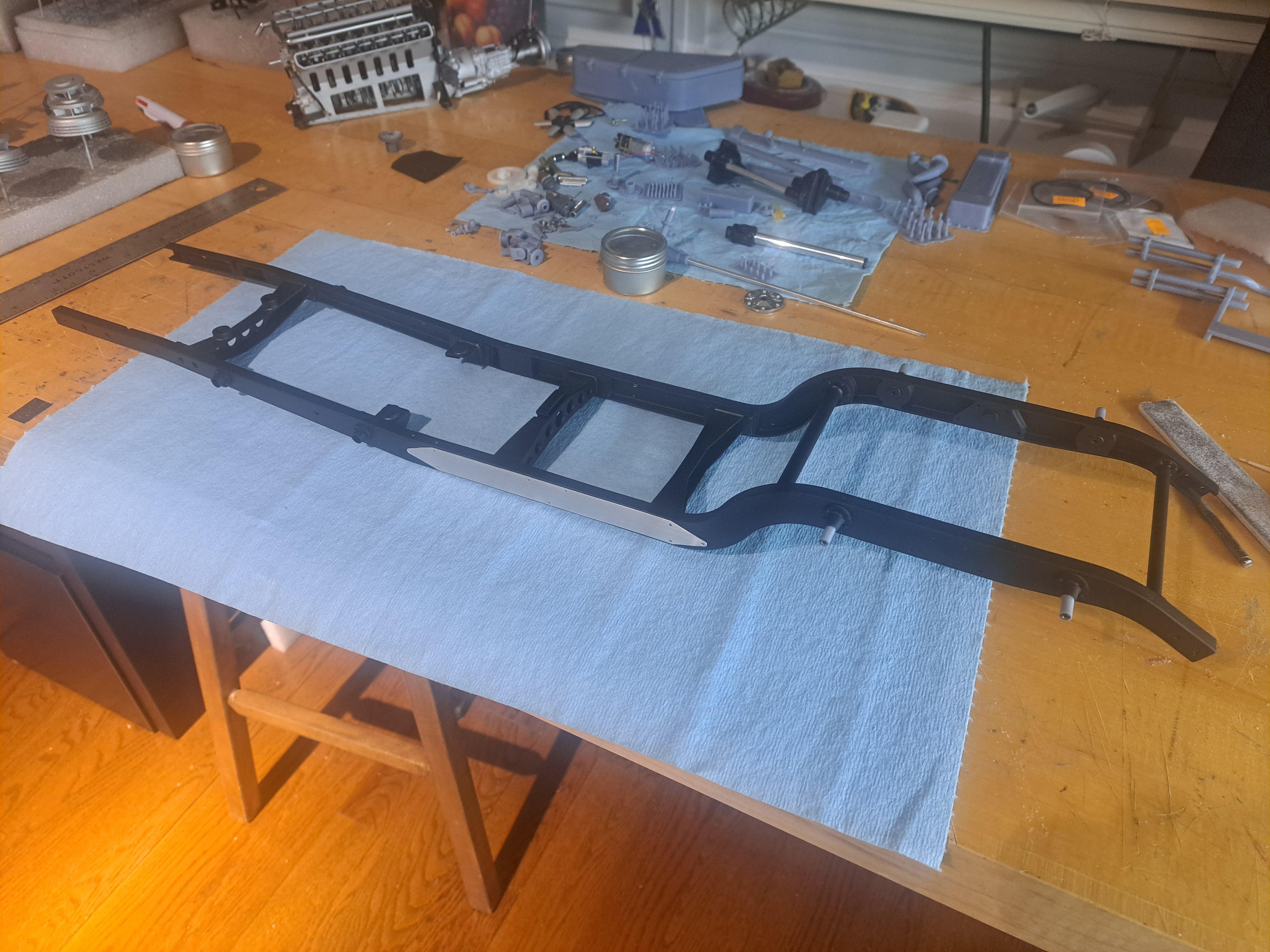
Finished painting all the frame parts using Revell's silk black (same color I used on the Bentley's body. I could find it in spray can format so I got the little plastic bottles instead. By adding a bit of revell aqua thinner (it's a water based paint) in a 3 paint to 1 thinner ratio, I got a very nice airbrushable consistency. I also made the aluminium stiffener plates that are installed on both sides of frame (still need to but the bolts in).